EasyManua.ls Logo

Sony STR-DG500 Service Manual

Sony STR-DG500
82 pages
To Next Page IconTo Next Page
Page #1 background imageLoading...
Page #1 background image
1
SERVICE MANUAL
US Model
Canadian Model
STR-DG500/DG600
AEP Model
UK Model
E Model
Australian Model
STR-DG500
STR-DG500/DG600
MULTI CHANNEL AV RECEIVER
AUDIO POWER SPECIFICATIONS
POWER OUTPUT AND TOTAL HARMONIC
DISTORTION:
(Models of area code US only)
With 8 ohm loads, both channels driven, from
20 – 20,000 Hz; rated 100 watts per channel
minimum RMS power, with no more than
0.09 % total harmonic distortion from 250
milliwatts to rated output.
Amplifier section
Power Output
Models of area code US, CND
Stereo Power Output
1)
, Reference Power Output
1) 2)
8 ohms 20 Hz – 20 kHz, THD 0.09 %
100 W + 100 W, 110 W/ch
8 ohms 1 kHz, THD 0.7 %
110 W + 110 W, 120 W/ch
8 ohms 1 kHz, THD 10 %
125 W + 125 W, 150 W/ch
Models of area code AEP, UK, E2, TW, AUS
Stereo Power Output
1)
, Reference Power Output
1) 2)
8 ohms 20 Hz – 20 kHz, THD 0.09 %
85 W + 85 W, 110 W/ch
8 ohms 1 kHz, THD 0.7 %
100 W + 100 W, 120 W/ch
8 ohms 1 kHz, THD 10 %
125 W + 125 W, 150 W/ch
SPECIFICATIONS
Models of area code KR
Stereo Power Output
1)
, Reference Power Output
1) 2)
8 ohms 20 Hz – 20 kHz, THD 0.09 %
85 W + 85 W
1)
,
70 W + 70 W
3)
, 110 W/ch
8 ohms 1 kHz, THD 0.7 %
100 W + 100 W
1)
,
90 W + 90 W
3)
, 120 W/ch
8 ohms 1 kHz, THD 10 %
125 W + 125 W
1)
,
110 W + 110 W
3)
, 150 W/ch
1) Measured under the following conditions:
Area code Power requirements
US, CND 120 V AC, 60 Hz
AEP, UK, KR 230 V AC, 50 Hz
E2, AUS 240 V AC, 50 Hz
TW 110 V AC, 60 Hz
2) Reference power output for front, center, surround
and surround back. Depending on the sound field
settings and the source, there may be no sound output.
3) Measured under the following conditions:
Area code Power requirements
KR 220 V AC, 50 Hz
Ver. 1.0 2006. 02
9-887-127-01
2006B04-1
© 2006. 02
Sony Corporation
Home Audio Division
Published by Sony Techno Create Corporation
Manufactured under license from Dolby Laboratories.
“Dolby”, “Pro Logic”, “Surround EX”, and the double-D
symbol are trademarks of Dolby Laboratories.
“DTS”, “DTS-ES”, “Neo:6”, and “DTS 96/24” are
trademarks of Digital Theater Systems, Inc.
– Continued on next page –
Photo: STR-DG600: Silver type
All manuals and user guides at all-guides.com
all-guides.com

Table of Contents

Other manuals for Sony STR-DG500

Question and Answer IconNeed help?

Do you have a question about the Sony STR-DG500 and is the answer not in the manual?

Sony STR-DG500 Specifications

General IconGeneral
Number of Channels5.1
HDMI Inputs2
HDMI Outputs1
Dolby DigitalYes
DTSYes
FM/AM TunerYes
Component Video Inputs2
Digital Audio Inputs2 Optical, 1 Coaxial
Analog Audio Inputs4
Component Video Output1
Power Output100 watts per channel
Output Power100W per channel (6 ohms, 1 kHz, THD 0.9%)
Surround Sound FormatsDolby Digital, DTS
Dimensions (W x H x D)430 x 157.5 x 298 mm
Frequency Response10 Hz - 50 kHz
InputsHDMI, Component Video, Digital Audio, Analog Audio
OutputsHDMI, Component Video

Summary

Section 1 General Information

Description and Location of Parts

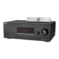
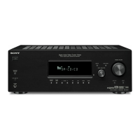
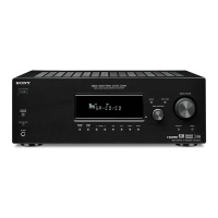
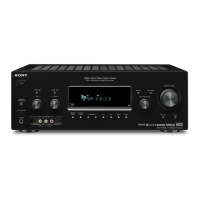
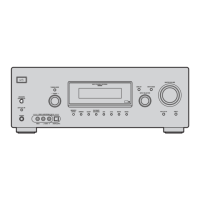
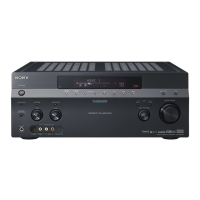
Details front panel components and their functions.

Display Indicators Explained

Explains the meaning of various indicators on the receiver's display.

Section 2 Disassembly Procedures

Case and Panel Disassembly

Guides on removing the unit's case and front/back panels.

Internal Board Disassembly

Instructions for disassembling digital, main, standby, and SB amp boards.

Section 3 Test Mode Operations

Service Test Mode Procedures

Procedures for activating various self-test modes for diagnostics.

Section 4 Diagrams and Schematics

Block Diagrams Overview

Functional diagrams of tuner, digital, video, XM, key/display, and power sections.

Printed Wiring Boards and Schematics

Detailed circuit schematics and PWB layouts for main, digital, video, speaker, etc.

Waveforms and IC Block Diagrams

Signal waveforms and functional blocks for key integrated circuits.

Section 5 Exploded Views

Assembly Part Breakdowns

Visual breakdown of parts for case, front panel, back panel, and chassis.

Section 6 Electrical Parts List

Component Identification and Listing

Comprehensive list of electronic components with part numbers and specifications.

Related product manuals