EasyManua.ls Logo

Sony STR-K780 Service Manual

Sony STR-K780
54 pages
To Next Page IconTo Next Page
Page #1 background imageLoading...
Page #1 background image
SERVICE MANUAL
Sony Corporation
Home Audio Division
Published by Sony Techno Create Corporation
AEP Model
UK Model
STR-K780
E Model
STR-K680/K780
Australian Model
STR-K780
MULTI CHANNEL AV RECEIVER
9-887-140-04
2006H16-1
© 2006.08
Ver. 1.3 2006.08
SPECIFICATIONS
STR-K680/K780
STR-K680 is the tuner and the amplifier section
in HT-DDW680, STR-K780 is the tuner and the
amplifier section in HT-DDW780/HTP-36DW.
Manufactured under license from Dolby Laboratories.
“Dolby”, “Pro Logic” and the double-D symbol are trademarks of
Dolby Laboratories.
“DTS” and “DTS Digital Surround” are registered trademarks of
Digital Theater Systems, Inc.
— Continued on next page —
Photo : STR-K780
Amplifier section
Power Output
1)
Models of area code SP, SP6
(6 ohms 1 kHz, THD 0.7%)
FRONT
2)
: 70 W/ch
CENTER
2)
: 70W
SUR
2)
: 70 W/ch
(6 ohms 1 kHz, THD 10%)
FRONT
2)
: 100 W/ch
CENTER
2)
:100 W
SUR
2)
: 100 W/ch
Models of area code AEP, UK, RU
(6 ohms 1 kHz, THD 0.7%)
FRONT
2)
: 85 W/ch
CENTER
2)
: 85 W
SUR
2)
8:5 W
/c
h
(6 ohms 1 kHz, THD 1
0
%)
FRONT
2)
: 122 W/ch
CENTER
2)
: 122 W
SUR
2)
: 122 W/c h
Models of area code AUS
(6 ohms 120 Hz–20 kHz, THD 0.09%)
FRONT
2)
: 50 W/ch
CENTER
2)
: 50 W
SUR
2)
: 50 W/ch
(6 ohms 1 kHz, THD 0.7%)
FRONT
2)
: 85 W/ch
CENTER
2)
: 85 W
SUR
2)
: 85 W/ch
(6 ohms 1 kHz, THD 10%)
FRONT
2)
: 122W/ch
CENTER
2)
: 12 2 W
SUR
2)
: 122W/ch
1)
Measured under the following conditions:
2)
Depending on the sound field settings and the
source, there may be no sound output.
Area code Power requirements
SP, SP6, AEP, UK, RU 230 V AC, 50 Hz
AR 230 V AC, 50 Hz
Models of area code E51, MX
Power Output
1)
(6 ohms 1 kHz, THD 0.7%)
FRONT
2)
: 70 W/ch
CENTER
2)
: 70 W
SUR
2)
: 70 W/ch
(6 ohms 100 Hz, THD 0.7%)
SUB WOOFER
2)
:
70 W
(6 ohms 1 kHz, THD 10%)
FRONT
2)
: 100 W/ch
CENTER
2)
: 100 W
SUR
2)
: 100 W/ch
(6 ohms 100 Hz, THD 10%)
SUB WOOFER
2)
:
10 0 W
E51, AUS 240 V AC, 50 Hz
MX 127 V AC, 60 Hz
Models of area code AR
Power Output
1)3)
(6 ohms 1 kHz, THD 0.7%)
FRONT
2)
: W/ch
1)
, 65 W/ch
3)
CENTER
2)
: W
1)
, 65 W
3)
SUR
2)
: W/ch
1)
, 65 W/ch
3)
(6 ohms 100 Hz, THD 0.7%)
SUB WOOFER
2)
: W
1)
, 65 W
3)
(6 ohms 1 kHz, THD 10%)
FRONT
2)
: 100
100
100
100
W/ch
1)
, 90 W/ch
3)
CENTER
2)
: W
1)
, 90 W
3)
SUR
2)
:W/ch
1)
, 90 W/ch
3)
(6 ohms 100 Hz, THD 10%)
SUB WOOFER
2)
:W
1)
, 90 W
3)
3)
Measured under the following conditions:
Area code Power requirements
AR 220 V AC, 50 Hz
70
70
70
70
Question and Answer IconNeed help?

Do you have a question about the Sony STR-K780 and is the answer not in the manual?

Sony STR-K780 Specifications

General IconGeneral
TypeAV receiver
Channels5.1
BluetoothNo
Total harmonic distortion0.09%
Power Output100W per channel
Audio Formats SupportedDolby Digital, DTS
Tuning rangeAM/FM
Power output (Surround)100W per channel
Digital inputs1 x coaxial, 2 x optical
Video ConnectionsComposite, Component
Frequency response28Hz - 20kHz

Summary

Product Specifications

Amplifier Section Power Output

Details power output for various area codes, conditions, and speaker configurations.

Model Identification and Area Codes

Component Handling & Safety Notes

Safety-Related Component Warning

Highlights critical components that require careful replacement for safe operation.

Section 1 General - Front Panel Controls

Front Panel Controls Overview

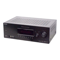
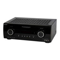
Describes the function of each button and indicator on the front panel.

Display Indicators Explained

Rear Panel Connections

Rear Panel Connections STR-K780 Model

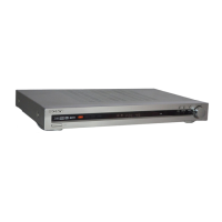
Details the input/output jacks and their functions for the STR-K780 model.

Remote Commander Operations

Remote Commander Buttons and Functions

Explains the operation of the remote commander and its assigned buttons.

Section 2 Test Modes

Factory Preset Mode

Resets all preset contents to default settings.

ADCC Factory Test Mode

Section 3 Diagrams

Circuit Board Locations

Identifies the physical locations of various circuit boards within the unit.

Block Diagram - Main Section

Printed Wiring Boards

Digital Board (Side A)

Shows the component layout for the digital board, side A.

Schematic Diagrams

Digital Board Schematic (1/3)

Provides the first part of the digital board schematic diagram.

Main Board Printed Wiring

Main Board Schematic (1/3)

IC Block Diagrams

Digital Board IC Block Diagrams

Illustrates the internal functional blocks of ICs on the digital board.

IC Pin Function Descriptions

Digital Board IC1101 Pin Functions

Details the pin assignments and functions for IC1101 on the digital board.

Section 4 Exploded Views

Front Panel Section Exploded View

Shows an exploded view of the front panel assembly and its parts.

Chassis Section Exploded View

Section 5 Electrical Parts List

Resistors

Lists resistor part numbers, descriptions, and specifications.

Capacitors

Diodes and Transistors

Jacks and Connectors

Related product manuals