EasyManua.ls Logo

Sony STR-KS360S User Manual

Sony STR-KS360S
70 pages
To Next Page IconTo Next Page
Page #1 background imageLoading...
Page #1 background image
SERVICE MANUAL
Sony Corporation
Audio&Video Business Group
Published by Sony Techno Create Corporation
STR-KS360/KS360S
SPECIFICATIONS
MULTI CHANNEL AV RECEIVER
9-889-446-01
2009C05-1
©
2009.03
US Model
Canadian Model
STR-KS360/KS360S
AEP Model
UK Model
Australian Model
STR-KS360S
Ver. 1.0 2009.03
STR-KS360 is the receiver section in US, Canadian models of HT-SS360.
STR-KS360S is the receiver section in HT-SF360 and AEP, UK models of HT-SS360.
This receiver incorporates Dolby* Digital and
Pro Logic Surround and the DTS ** Digital
Surround System.
* Manufactured under license from Dolby
Laboratories. Dolby, Pro Logic, and the
double-D symbol are trademarks of Dolby
Laboratories.
** Manufactured under license under U.S.
Patent #’s: 5,451,942; 5,956, 674; 5,974,
380; 5,978,762; 6,487,535 & other U.S.
and worldwide patents issued & pending.
DTS andDTS Digital Surround are
registered trademarks and the DTS logos
and Symbol are trademarks of DTS, Inc. ©
1996-2008 DTS, Inc. All Rights Reserved.
This receiver incorporates High-Definition
HDMI, the HDMI logo and High-Definition
Multimedia Interface (HDMI
TM
) technology.
LLC.
registered trademarks of HDMI Licensing
Multimedia Interface are trademarks or
“x.v.Color and x.v.Color” logo are
“BRAVIA” is a trademarks of Sony
“S-AIR” and its logo are trademarks of Sony
trademarks of Sony Corporation.
Corporation.
Corporation.
About area codes
The area code of the receiver you purchased is
shown on the lower portion of the rear panel (see
the illustration below).
Any differences in operation, according to the area
code, are clearly indicated in the text, for example,
“Models of area code AA only”.
FRONT R
SPEAKERS
FRONT L SUR R SUR L CENTER
SUBWOOFER
Area code
Models of area code CEL, CEK, AU
Power Output
1)
Stereo mode (rated) 108 W + 108 W
(3 ohms at 1 kHz, THD 1%)
Surround mode (reference)
RMS Output
(3 ohms at 1 kHz, THD 10%)
FRONT
2)
: 143 W/ch
CENTER
2)
: 143 W
SUR
2)
: 143 W/ch
(1.5 ohms at 70 Hz,
THD 10%)
SUBWOOFER
2)
: 285 W
AUDIO POWER
SPECIFICATIONS
POWER OUTPUT AND TOTAL
HARMONIC DISTORTION:
(Models of area code U, UC only)
With 3 ohm loads, both channels driven, from
170 20,000 Hz; rated 84 watts per channel
minimum RMS power, with no more than 1%
total harmonic distortion from 250 milliwatts
to rated output.
Amplifier section
Models of area code U, UC, CA
Power Output
1)
Stereo mode (rated) 84 W + 84 W
(3 ohms at 170
20,000 Hz, THD 1%)
Surround mode (reference)
RMS Output
(3 ohms at 1 kHz,
THD 10%)
FRONT
2)
: 143 W/ch
CENTER
2)
: 143 W
SUR
2)
: 143 W/ch
(1.5 ohms at 70 Hz,
THD 10%)
SUBWOOFER
2)
: 285 W
1)
Measured under the following conditions:
2)
Reference power output for front, center, surround
speakers and subwoofer. Depending on the sound
field settings and the source, there may be no
sound output.
Inputs
Analog Sensitivity: 1 V/50 kohms
Digital (Coaxial) Impedance: 75 ohms
Tone
Gain levels ±10 dB, 0.5 dB step
Reproduction frequency range:
28–20,000Hz
FM tuner section
Tuning range 87.5 108.0 MHz
Antenna FM wire antenna
Antenna terminals 75 ohms, unbalanced
Intermediate frequency
10.7 MHz
AM tuner section
Tuning range
Antenna Loop antenna
Intermediate frequency
450 kHz
General
Power requirements
Power output (DIGITAL MEDIA PORT)
DC OUT: 5 V, 700 mA MAX
Area code Power requirements
U, UC, CA
AU
Area code Tuning scale
10 kHz step 9 kHz step
CEL, CEK 531
530
1,602 kHz
Area code Power requirements
CEL, CEK
AU
CEL, CEK
120 V AC, 60 Hz
230 V AC, 50 Hz
240 V AC, 50 Hz
U, UC, CA, AU
1,710 kHz
531
1,710 kHz
U, UC, CA
120 V AC, 60 Hz
220 – 240 V AC, 50/60 Hz
240 V AC, 50 Hz
Power consumption
Power consumption (during standby mode)
0.3 W (When Control for
HDMI and S-AIR standby
are off)
Dimensions (w/h/d) (Approx.)
17 × 2 5/8 × 13 1/8 inches
(430 × 66.5 × 333 mm)
including projecting parts
and controls
Mass (Approx.) 3.4 kg (7 lb 8 oz)
Area code Power consumption
CEK, AU
U, UC, CA, CEL,
165 W
Design and specifications are subject to
change without notice.
Photo: STR-KS360S
w
w
w
.
x
i
a
o
y
u
1
6
3
.
c
o
m
Q
Q
3
7
6
3
1
5
1
5
0
9
9
2
8
9
4
2
9
8
T
E
L
1
3
9
4
2
2
9
6
5
1
3
9
9
2
8
9
4
2
9
8
0
5
1
5
1
3
6
7
3
Q
Q
TEL 13942296513 QQ 376315150 892498299
http://www.xiaoyu163.com
Question and Answer IconNeed help?

Do you have a question about the Sony STR-KS360S and is the answer not in the manual?

Sony STR-KS360S Specifications

General IconGeneral
TypeAV receiver
Number of Channels5.1
Digital Audio Inputs (Coaxial)1
HDMI Output1
Component Video Output1
Headphone JackYes
TunerAM/FM
Remote ControlYes
Surround Sound FormatsDolby Digital, DTS

Summary

Servicing Notes

Unleaded Solder Characteristics

Details on the properties and handling of unleaded solder for PCB assembly.

HDMI Board IC Replacement Note

Specific instruction for replacing IC3511 and IC3513 on the HDMI board.

General

Component Location and Description

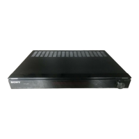
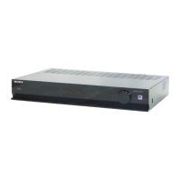
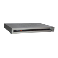
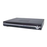
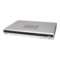
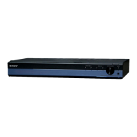
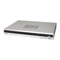
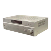
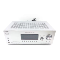
Identifies and describes the location of front and rear panel parts of the receiver.

Remote Commander Operation (US/Canadian Models)

Explains basic, tuner, and DMPORT operations for US/Canadian remote commander.

Remote Commander Operation (AEP/UK/Australian Models)

Explains operations for AEP, UK, and Australian remote commander models.

Disassembly

Disassembly Flowchart

Provides a step-by-step flow for disassembling the unit.

Case Disassembly Procedure

Instructions for removing and disassembling the main case.

S-AIR Board Removal (KS360S)

Procedure for removing the S-AIR board from the KS360S model.

IO Board Removal

Steps for removing the Input/Output (IO) board from the unit.

Front Panel Block Disassembly

Guide for disassembling the front panel assembly.

Main Board Removal

Procedure for removing the main circuit board.

Test Mode

Cold Reset Procedure

Resets all preset contents, used after repair completion.

Entering Test Mode

Instructions on how to access the unit's diagnostic test modes.

Panel Test Operations

Covers pattern and key check procedures within the test mode.

Software Version and Destination Display

Procedure to display model, destination, and software version.

HDMI UCOM Update

Procedure to check and update HDMI microprocessor software version.

DMPORT Test Procedures

Tests for DMPORT functionality, including check jig and device tests.

S-AIR Test Modes (KS360S)

Details various S-AIR test modes like power, NAMG, version, and encryption.

FM Auto Stop Check

Procedure to verify FM tuner auto stop function with a signal generator.

Diagrams

Block Diagram - Main Section

Overview of the main signal flow and component interconnections.

Block Diagram - HDMI Section

Diagram illustrating the signal paths and components within the HDMI section.

Block Diagram - DSP/S-AIR Section

Shows the block diagram for the DSP and S-AIR signal processing sections.

Block Diagram - AMP Section

Illustrates the block diagram of the audio amplifier section.

Block Diagram - Power Supply Section

Diagram showing the power supply unit's block level connections.

Circuit Boards Location Diagram

Diagram indicating the physical location of various circuit boards within the unit.

Printed Wiring Board - Main Board (Component Side)

Layout of components on the main board's component side.

Printed Wiring Board - Main Board (Conductor Side)

Layout of traces on the main board's conductor side.

Schematic Diagram - Main Board (1/6)

Part 1 of 6 schematic diagrams for the main board circuitry.

Schematic Diagram - Main Board (2/6)

Part 2 of 6 schematic diagrams for the main board circuitry.

Schematic Diagram - Main Board (3/6)

Part 3 of 6 schematic diagrams for the main board circuitry.

Schematic Diagram - Main Board (4/6)

Part 4 of 6 schematic diagrams for the main board circuitry.

Schematic Diagram - Main Board (5/6)

Part 5 of 6 schematic diagrams for the main board circuitry.

Schematic Diagram - Main Board (6/6)

Part 6 of 6 schematic diagrams for the main board circuitry.

Printed Wiring Board - S-AIR Board (KS360S)

Layout of components on the S-AIR board for KS360S models.

Schematic Diagram - S-AIR Board (KS360S)

Schematic for the S-AIR board, applicable to KS360S models.

Printed Wiring Board - IO Board

Component layout for the Input/Output (IO) board.

Schematic Diagram - IO Board

Schematic diagram detailing the Input/Output (IO) board circuitry.

Schematic Diagram - HDMI Board (1/2)

Part 1 of 2 schematic diagrams for the HDMI board.

Schematic Diagram - HDMI Board (2/2)

Part 2 of 2 schematic diagrams for the HDMI board.

Printed Wiring Board - HDMI Board

Component layout for the HDMI board.

Printed Wiring Boards - PANEL Section

Component layout for the display and IR boards.

Schematic Diagram - PANEL Section

Schematic for the display and IR boards.

Printed Wiring Board - SMPS Board

Component layout for the Switch Mode Power Supply (SMPS) board.

Schematic Diagram - SMPS Board

Schematic detailing the Switch Mode Power Supply (SMPS) board.

Waveforms

Main Board Waveforms

Illustrates typical waveforms observed on the main board ICs.

HDMI Board Waveforms

Displays characteristic waveforms from HDMI board ICs.

Display Board Waveforms

Shows typical waveforms from the display board circuitry.

IC Block Diagrams

Main Board IC Block Diagrams

Internal block diagrams for key ICs on the main board.

IC Pin Function Description

Main Board IC1003 Pinout

Detailed pin functions for IC1003 (DSP) on the main board.

Main Board IC1005 Pinout

Detailed pin functions for IC1005 (System Controller) on the main board.

HDMI Board IC3511 Pinout

Detailed pin functions for IC3511 (HDMI Receiver) on the HDMI board.

HDMI Board IC3519 Pinout

Detailed pin functions for IC3519 (HDMI Controller) on the HDMI board.

Exploded Views

Case and S-AIR Board Exploded View

Exploded view showing the main case and S-AIR board components.

Front Panel Exploded View

Exploded diagram of the front panel assembly and associated parts.

Main Board Exploded View

Exploded view detailing the main board and its mounting components.
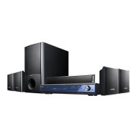
Electrical Parts List

Revision History

Related product manuals