EasyManua.ls Logo

Sony STR-KSL60 User Manual

Sony STR-KSL60
31 pages
To Next Page IconTo Next Page
Page #1 background imageLoading...
Page #1 background image
STR-KSL60
AEP Model
UK Model
SERVICE MANUAL
HOME THEATER SYSTEM
Sony Corporation
Home Audio Company
Published by Sony Engineering Corporation
9-961-218-01
2003H1678-1
© 2003.08
SPECIFICATIONS
Ver 1.0 2003. 08
Manufactured under license from Dolby Laboratories.
“Dolby”, “Pro Logic” and the double-D symbol are
trademarks of Dolby Laboratories.
STR-KSL60 is the receiver section in HT-SL60/SL65.
— Continued on next page —
Amplifier section
POWER OUTPUT
Rated Power Output at Stereo Mode
(8 ohms 1 kHz, THD 0.7 %)
25 W + 25 W
Reference Power Output
(8 ohms 1 kHz, THD 10 %)
FRONT
1)
: 35 W/ch
CENTER
1)
: 35 W
SURR
1)
: 35 W/ch
Depending on the sound field settings and the
source, there may be no sound output.
Frequency response
TV/SAT, DVD, VIDEO: 10 Hz – 50 kHz
+0.5/–3 dB (with sound
field and tone by passed)
Inputs (Analog)
TV/SAT, DVD, VIDEO: Sensitivity: 250 mV
Impedance: 50 kilohms
S/N
3)
: 96 dB
(A, 250 mV
4)
)
3) INPUT SHORT (with sound field and tone by
passed).
4) Weighted network, input level.
Outputs
SUB WOOFER Voltage: 2 V
Impedance: 1 kilohms
Tone
Gain levels: ±6 dB, 1 dB step
Video section
Inputs
Video: 1 Vp-p, 75 ohms
Outputs
Video: 1 Vp-p, 75 ohms
FM tuner section
Tuning range 87.5 – 108.0 MHz
Antenna terminals 75 ohms, unbalanced
Intermediate frequency
10.7 MHz
Sensitivity
Mono: 18.3 dBf, 2.2 µV/75 ohms
Stereo: 38.3 dBf, 22.5 µV/75
ohms
Usable sensitivity 11.2 dBf, 1 µV/75 ohms
S/N
Mono: 76 dB
Stereo: 70 dB
Harmonic distortion at 1 kHz
Mono: 0.3%
Stereo: 0.5%
Separation 45 dB at 1 kHz
Frequency response 30 Hz – 15 kHz
+0.5/–2 dB
Selectivity 60 dB at 400 kHz
Inputs (Digital)
DVD (Coaxial) Sensitivity: –
Impedance: 75 ohms
S/N: 100 dB
(A, 20 kHz LPF)
DVD, TV/SAT (Optical) Sensitivity: –
Impedance:
S/N: 100 dB
(A, 20 kHz LPF)
AM tuner section
Tuning range
With 9-kHz tuning scale: 531 – 1602 kHz
Antenna Loop antenna
Intermediate frequency
450 kHz
Usable sensitivity 50 dB/m (at 999 kHz)
S/N 54 dB (at 50 mV/m)
Harmonic distortion 0.5% (50 mV/m, 400 Hz)
Selectivity At 9 kHz: 35 dB
General
Power requirements
230 V AC, 50/60 Hz
Power consumption
130 W
Power consumption
(during standby mode)
0.3 W
Dimensions (w/h/d)
430 56 290 mm
including projecting parts
and controls
Mass (Approx.)
4.5 kg
××
1)
Question and Answer IconNeed help?

Do you have a question about the Sony STR-KSL60 and is the answer not in the manual?

Sony STR-KSL60 Specifications

General IconGeneral
BrandSony
ModelSTR-KSL60
CategoryReceiver
LanguageEnglish

Summary

SPECIFICATIONS

Amplifier section

Details of the amplifier's power output and frequency response.

AM tuner section

Technical specifications for the AM tuning range and sensitivity.

FM tuner section

Technical specifications for the FM tuning range and sensitivity.

General

Overall technical specifications like power requirements and dimensions.

SECTION 1 GENERAL

List of Button Locations and Reference Pages

Guide to button locations and corresponding page references.

Main unit

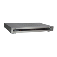
Identification of controls and indicators on the main unit.

SECTION 2 TEST MODE

FACTORY PRESET MODE

Resets all preset contents to default factory settings.

RDS AUTOBETICAL MODE

Scans and sets up receivable broadcasts automatically.

MICRO/NORMAL SPEAKER SELECTION MODE

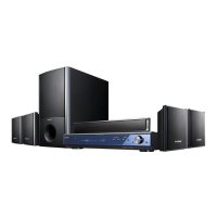
Allows selection between micro or normal speaker modes.

SOUND FIELD CLEAR MODE

Clears all preset sound field settings.

ALL CLEAR MODE

Clears all preset values and settings.

SOFTWARE VERSION DISPLAY MODE

Displays the model name, destination, and software version.

KEY CHECK MODE

Verifies the functionality of all buttons on the unit.

FLUORESCENT INDICATOR TUBE TEST MODE

Tests all segments of the fluorescent indicator tube.

TUNER CHECK MODE

Performs a check of the tuner's functionality.

SECTION 3 DIAGRAMS

Circuit Boards Location

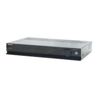
Identifies the physical location of various circuit boards within the unit.

Waveforms

Displays typical waveforms for diagnostic purposes.

BLOCK DIAGRAMS - MAIN SECTION

High-level overview of the main signal flow and components.

DISPLAY/POWER SECTION

Diagram illustrating the display and power supply circuits.

PRINTED WIRING BOARD - DIGITAL SECTION

Layout of components and traces on the digital section's PCB.

Semiconductor Location

Pinpoints the location of semiconductor components on the digital board.

SCHEMATIC DIAGRAM - DIGITAL (1/2) SECTION

Detailed circuit schematic for the digital section.

SCHEMATIC DIAGRAM - DIGITAL (2/2) SECTION

Continuation of the digital section schematic.

PRINTED WIRING BOARD - MAIN/STANDBY SECTION

Layout of components and traces on the main/standby section's PCB.

SCHEMATIC DIAGRAM - MAIN (1/2) SECTION

Detailed circuit schematic for the main section.

SCHEMATIC DIAGRAM - MAIN (2/2)/STANDBY SECTION

Continuation of the main/standby section schematic.

PRINTED WIRING BOARD - DISPLAY SECTION

Layout of components and traces on the display section's PCB.

SCHEMATIC DIAGRAM - DISPLAY SECTION

Detailed circuit schematic for the display section.

IC BLOCK DIAGRAM

Block diagrams illustrating the internal functions of key ICs.

IC PIN FUNCTION DESCRIPTIONS

Explains the function of each pin for specific integrated circuits.

SECTION 4 EXPLODED VIEWS

4-1. FRONT PANEL SECTION

Illustrates the parts and assembly of the front panel.

4-2. CHASSIS SECTION

Shows the breakdown of the main chassis and internal components.

SECTION 5 ELECTRICAL PARTS LIST

CAPACITORS

List of all capacitors used in the device with their specifications.

COILS

List of all coils used in the device with their specifications.

RESISTORS

List of all resistors used in the device with their specifications.

SEMICONDUCTORS

List of all semiconductor components with their specifications.

Related product manuals