SERVICE MANUAL
MULTI CHANNEL AV RECEIVER
AEP Model
UK Model
E Model
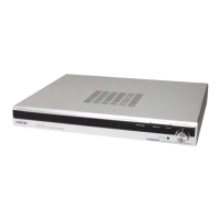
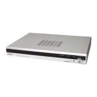
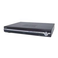
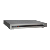
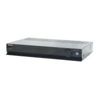
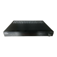
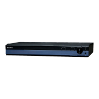
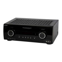
STR-KS1000
• STR-KS1000 is the receiver section in HT-SF1000/SS1000.
Ver. 1.2 2006.08
9-887-058-03
2006H05-1
© 2006.08
Sony Corporation
Home Audio Division
Published by Sony Techno Create Corporation
This receiver incorporates Dolby* Digital and Pro
Logic Surround and the DTS** Digital Surround
System.
*Manufactured under license from Dolby
Laboratories.
“Dolby”, “Pro Logic” and the double-D symbol
are trademarks of Dolby Laboratories.
**“DTS” and “DTS Digital Surround” are
registered trademarks of Digital Theater
Systems, Inc.
– Continued on next page –
SPECIFICATIONS
Amplifier section
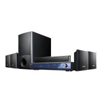
HT-SF1000 only
Power Output
1)
Stereo mode (rated) 70 W + 70 W
(4 ohms at 1 kHz, 0.7%)
Music power output (reference)
FRONT
2)
: 143 W/ch
(With SS-FSP1000)
CENTER
2)
: 143 W
(With SS-CNP1000F)
SUR
2)
: 143 W/ch
(With SS-FRP1000)
SUBWOOFER
2)
: 28
5 W
(With SS-WP1000)
HT-SS1000 only
Power Output
1)
Stereo mode (rated) 70 W + 70 W
(4 ohms at 1 kHz, 0.7%)
Music power output (reference)
FRONT
2)
: 143 W/ch
(With SS-MSP1000)
CENTER
2)
: 143 W
(With SS-CNP1000)
SUR
2)
: 143 W/ch
(With SS-SRP1000)
SUBWOOFER
2)
: 285 W
(With SS-WP1000)
1)
Measured under the following conditions:
2)
Depending on the sound field settings and the
source, there may be no sound output.
Inputs (Analog)
Area code Power requirements
CEL, CEK, SP, MY,
AR
230 V AC, 50 Hz
E51
240 V AC, 50 Hz
SA-CD/CD,
VIDEO 1, 2
Sensitivity: 1 V
Impedance: 50 kohms
Tone
FM tuner section
Tuning range 87.5 - 108.0 MHz
Antenna FM wire antenna
Antenna terminals 75 ohms, unbalanced
Intermediate frequency
10.7 MHz
AM tuner section
Tuning range
Models of area code CEL, CEK SP, MY,
With 9-kHz tuning scale:
531 − 1,602 kHz
Gain levels ±6 dB, 1 dB step
Inputs (Digital)
Reproduction frequency range:
28 − 20,000 Hz
DVD (Coaxial) Sensitivity: −
Impedance: 75 ohms
VIDEO 2, SA-CD/
CD (Optical)
Sensitivity: −
Impedance: −
Models of area code E51
With 10-kHz tuning scale:
530 − 1,610 kHz
3)
With 9-kHz tuning scale:
531 − 1,602 kHz
3)
Models of area code AR
With 10-kHz tuning scale:
530 − 1,610 kHz
Antenna Loop antenna
Intermediate frequency
450 kHz
3)
You can change the AM tuning scale to 9 kHz or
10 kHz. After tuning in any AM station, turn off
the receiver. While holding down PRESET
TUNING +, press ?/1. All preset stations will be
erased when you change the tuning scale. To reset
the scale to 10 kHz (or 9 kHz), repeat the
procedure.
This receiver incorporates High-Definition
Multimedia Interface (HDMI
TM
) technology.
HDMI, the HDMI logo and High-Definition
Multimedia Interface are trademarks or registered
trademarks of HDMI Licensing LLC.
w
w
w
.
x
i
a
o
y
u
1
6
3
.
c
o
m
Q
Q
3
7
6
3
1
5
1
5
0
9
9
2
8
9
4
2
9
8
T
E
L
1
3
9
4
2
2
9
6
5
1
3
9
9
2
8
9
4
2
9
8
0
5
1
5
1
3
6
7
3
Q
Q
TEL 13942296513 QQ 376315150 892498299
TEL 13942296513 QQ 376315150 892498299
http://www.xiaoyu163.com
http://www.xiaoyu163.com