EasyManua.ls Logo

Sony STR-KM5500 Service Manual

Sony STR-KM5500
72 pages
To Next Page IconTo Next Page
Page #1 background imageLoading...
Page #1 background image
SERVICE MANUAL
Sony Corporation
Audio&Video Business Group
Published by Sony EMCS (Malaysia) PG Tec
STR-KM5500
SPECIFICATIONS
MULTI CHANNEL AV RECEIVER
9-890-520-03
2009K80-1
©
2009.11
E Model
Ver. 1.2 2009.11
STR-KM5500 is the receiver section in HT-DDW5500.
This receiver incorporates Dolby* Digital and Pro Logic Surround and the DTS** Digital Surround System.
* Manufactured under license from Dolby Laboratories. Dolby, Pro Logic, and the double-D symbol are
trademarks of Dolby Laboratories.
** Manufactured under license under U.S. Patent #’s: 5,451,942; 5,956,674; 5,974,380; 5,978,762; 6,226,616;
6,487,535; 7,003,467; 7,212,872 & other U.S. and worldwide patents issued & pending. DTS, DTS
Digital Surround, ES, and Neo:6 are registered trademarks and the DTS logos, Symbol and DTS 96/24
are trademarks of DTS, Inc. © 1996-2008 DTS, Inc. All Rights Reserved.
This receiver incorporates High-Definition Multimedia Interface (HDMI ) technology.
HDMI, the HDMI logo and High-Definition Multimedia Interface are trademarks or registered trademarks
of HDMI Licensing LLC.
TM
– Continued on next page –
Amplifier section
s Receiver (STR-KM5500)
Power Output
Models of area code SP, E51, AR, TH, SAF,
EA, MY
Stereo mode output (rated) (6 ohms, 1 kHz,
THD 1%)
100 W + 100 W
1)
90 W + 90 W
2)
Surround mode output (reference)
3)
RMS output
FRONT: 185 W per channel
1)
170 W per channel
2)
(with SS-MSP7500)
CENTER: 185 W
1)
170 W
2)
(with SS-CNP7500)
SURROUND: 185 W per channel
1)
170 W per channel
2)
(with SS-SRP7500)
SURROUND BACK:
185 W
1)
170 W
2)
(with SS-SRP7500)
1)
Measured under the following conditions:
2)
Measured under the following conditions:
Area code Power requirements
E51, SP, SAF, MY 240 V AC, 50 Hz
EA 127 V AC, 60 Hz
AR, TH 230 V AC, 50 Hz
Area code Power requirements
AR, TH 220 V AC, 50 Hz
3)
Reference power output for front, center, surround
and surround back speakers. Depending on the
sound field settings and the source, there may be
no sound output.
Inputs
Analog Sensitivity: 800 mV/
50 kohms
Digital (Coaxial) Impedance: 75 ohms
Outputs (Analog)
AUDIO OUT Voltage: 800 mV/
10 kohms
SUBWOOFER Voltage: 2 V/1 kohm
Tone
Gain levels
±6 dB, 1 dB step
Reproduction frequency range:
28 – 20,000 Hz
FM tuner section
Tuning range 87.5 – 108.0 MHz
Antenna FM wire antenna
Antenna terminals 75 ohms, unbalanced
Intermediate frequency
10.7 MHz
AM tuner section
Tuning range
Area code Tuning scale
10 kHz step 9 kHz step
AR, E51 530 –
1,710 kHz
531 –
1,710 kHz
SP, SAF, MY, TH 530 –
1,610 kHz
531 –
1,602 kHz
135 AE
1,602 kHz
Question and Answer IconNeed help?

Do you have a question about the Sony STR-KM5500 and is the answer not in the manual?

Sony STR-KM5500 Specifications

General IconGeneral
BrandSony
ModelSTR-KM5500
CategoryReceiver
LanguageEnglish

Summary

Receiver Specifications

Amplifier and Tuner Specifications

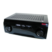
Covers power output, amplifier specs, and tuner frequency ranges.

Servicing Notes and General Information

Unit Disassembly Procedures Overview

Step-by-step guide for disassembling the unit into major sections.

Chip Component Handling and Model Identification

Unleaded Solder and Model Identification

Characteristics of unleaded solder and model-specific part numbers.

Front Panel Description

Front Panel Controls and Functions

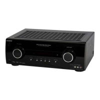
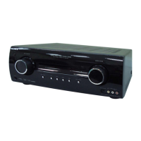
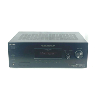
Explains the function of each control and indicator on the front panel.

Display Indicators Overview

Input and Dolby Pro Logic Indicators

Details on input source and Dolby Pro Logic indicator functions.

Display Indicators - DTS and Channel Information

DTS Indicators and Playback Channel Display

Explains DTS indicators and how playback channels are shown.

Rear Panel Connections Overview

Digital, Antenna, and Video Connections

Details on digital, antenna, and video input/output connectors.

Remote Commander Operation

Remote Commander Buttons - Power, Input, Volume

Explains functions of power, input selection, and volume control buttons.

Remote Commander Button Functions (Part 2)

Remote Commander Buttons - Menu, Playback, Tuning

Details menu navigation, playback control, and tuning functions.

Remote Commander Button Functions (Part 3)

Remote Commander Operation Notes and Tips

Notes on how remote functions may vary by model or component.

Disassembly Procedures - Case Removal

Disassembly Flow and Case Removal Steps

Overall flow chart and specific steps for case removal.

Disassembly Procedures - Panel Sections

Back Panel and Front Panel Disassembly Details

Details on removing back panel, associated boards, and front panel assembly.

Disassembly Procedures - Board Removal

Digital AB and Main Board Removal Steps

Details on removing the digital AB board and main board assembly.

Test Modes - Tuner, Key, and Display Checks

Test Modes - Swap All and Shipment Procedures

Procedures for Swap All mode and Shipment mode for factory reset.

Test Modes - DCAC, VACS Control, and History

DCAC DSP Data Line and Board Checking

Checking DCAC DSP data integrity and board functionality.

Electrical Check - FM Auto Stop Function

FM Auto Stop Check Procedure Details

Step-by-step guide for performing the FM auto stop test.

Circuit Board Locations Diagram

AC SELECT Board Location Specifics

Shows the location of the AC SELECT board, specific to certain models.

Block Diagrams - Tuner, Audio, and Digital AB Sections

Digital AB Section Block Diagram Details

Part of the block diagram showing the Digital AB section.

Block Diagrams - Digital AB Section Details

6CH DAC IC (IC1452) Block Diagram

Block diagram for the 6CH DAC IC, detailing its inputs and outputs.

Block Diagrams - Video Section Details

Component Video Select IC Block Diagram

Block diagram for the component video select IC.

Block Diagrams - HDMI Section Details

HDMI Receiver/Transceiver IC Block Diagram

Block diagram for the main HDMI receiver/transceiver IC.

Block Diagrams - Key/Display Section Details

FL Display Driver IC Block Diagram

Block diagram for the FL display driver IC.

Block Diagrams - Power Section Details

Power Amplifier Stages Schematic Details

Details the pre-driver and power amplifier stages for each channel.

Printed Wiring Board and Schematic Notes

Waveforms on DIGITAL AB Board

Displays sample waveforms for key ICs on the DIGITAL AB board.

Main Board Layout and Component Locations

Main Board Semiconductor Component Locations

Identifies semiconductor components and their locations on the main board.

Main Board Schematic (1/3)

Main Board Power Amplifier Circuits Schematic

Schematic details of the power amplifier output stages for each channel.

Main Board Schematic (2/3)

Main Board IC Connections Schematic

Schematic showing connections to major ICs on the main board.

Main Board Schematic (3/3)

Main Board Power Supply and Relay Circuits Schematic

Schematic details of power supply regulators and relay control circuits.

DIGITAL AB Board Layout (Side A)

DIGITAL AB Board Semiconductor Locations (Side A)

Lists semiconductor components and their positions on Side A of the DIGITAL AB board.

DIGITAL AB Board Layout (Side B)

DIGITAL AB Board Component Layout (Side B)

General component layout for Side B of the DIGITAL AB board.

DIGITAL AB Board Schematic (1/3)

DIGITAL AB Board IC Connections Schematic (Part 1)

Schematic details for specific ICs on the DIGITAL AB board.

DIGITAL AB Board Schematic (2/3)

DIGITAL AB Board Microcontroller and DSP Connections Schematic

Schematic showing connections to the microcontroller and DSP ICs.

DIGITAL AB Board Schematic (3/3)

DIGITAL AB Board Power and Control Signals Schematic

Schematic detailing power supply lines and control signals on the DIGITAL AB board.

VIDEO STANDBY SUPPLY Board Layout

VIDEO STANDBY SUPPLY Board Component Locations

Lists semiconductor components and their positions on the video standby supply board.

VIDEO STANDBY SUPPLY Board Schematic

VIDEO STANDBY SUPPLY Board ICs and Power Regulation Schematic

Schematic details of ICs and power regulation circuits on the video standby supply board.

HDMI SW Board Layout

HDMI SW Board Component Locations

Lists semiconductor components and their positions on the HDMI SW board.

HDMI SW Board Schematic

HDMI SW Board ICs and Signal Routing Schematic

Schematic details of ICs and signal routing for the HDMI interface.

VIDEO2 DCAC and HEADPHONE Boards Layout

VIDEO2 DCAC and HEADPHONE Board Components

Component layout and semiconductor locations for VIDEO2 DCAC and HEADPHONE boards.

VIDEO2 DCAC and HEADPHONE Boards Schematic

VIDEO2 DCAC Board Schematic Details

Schematic details for the VIDEO2 DCAC board, including IC connections.

DISPLAY and POWER Boards Layout

DISPLAY and POWER Board Component Locations

Lists semiconductor components and their positions on the DISPLAY and POWER boards.

DISPLAY and POWER Boards Schematic

Display Board Schematic Details (IC102)

Schematic details for the display board, focusing on the display driver IC.

TEMP-SENSOR and CONNECTION Boards Layout

TEMP-SENSOR Board Connections Diagram

Shows connections and components on the TEMP-SENSOR board.

AC SELECT Section for Specific Models

AC SELECT Board Schematic Diagram

Schematic detailing the AC voltage selection circuitry.

Key IC Block Diagrams Overview

IC400 BD3471KS2 Block Diagram

Block diagram for the BD3471KS2 IC on the main board.

IC Block Diagrams - Digital AB Board ICs

IC1452 WM8768GEDS/R Block Diagram

Block diagram for the WM8768GEDS/R IC used for audio DAC.

IC Block Diagrams - DIGITAL AB and HDMI SW ICs

IC1201 LC89058W-E Block Diagram

Block diagram for the LC89058W-E IC used for demo lock detection.

IC Block Diagrams - Analog Switches and EEPROM

IC220 NJM2586AM Block Diagram

Block diagram for the NJM2586AM analog switch IC.

IC Block Diagrams - HDMI SW Board ICs

IC5001 TMDS341PFCR Block Diagram

Block diagram for the TMDS341PFCR HDMI interface IC.

IC Block Diagrams - Display and HDMI SW Board ICs

IC102 ML9208-03GAZ03B Block Diagram

Block diagram for the ML9208-03GAZ03B display driver IC.

IC Pin Function Descriptions - IC1101 SYSTEM CONTROLLER

IC1101 Pin Functions - DIR and Input Signals

Pin descriptions for DIR interface and input selection signals.

IC Pin Function Descriptions - IC1101 Continued

IC1101 Pin Functions - Relay Controls and Display Signals

Pin details for relay control, HDMI detection, and display driver signals.

IC Pin Function Descriptions - IC1501 DSP EX3

IC1501 Pin Functions - Power and Clock Signals

Pin descriptions for power supply, ground, and clock signals of the DSP IC.

IC Pin Function Descriptions - IC1501 Continued

IC1501 Pin Functions - Audio Data and Control Signals

Pin details for PCM audio data, clock, and control signals.

IC Pin Function Descriptions - IC1501 Final Functions

IC1501 Pin Functions - System Control and Clock Signals

Pin descriptions for system control interface and clock signals.

Exploded View - Unit Case Disassembly

Case Exploded View and Associated Parts

Detailed diagram of the case and associated screws for removal.

Exploded View - Front Panel Assembly

Front Panel Assembly Parts Identification

Lists parts included with or for the front panel assembly.

Exploded View - Back Panel Section

Back Panel and Connected Boards Identification

Details the back panel, fuses, connectors, and tuner module.

Exploded View - Chassis Section Components

Chassis Section Components Identification

Identifies main boards, transistors, and transformers within the chassis.

Electrical Parts List - AC Select and Digital AB Boards

AC Select Board Electrical Parts List

Component details for the AC Select board, including capacitors and connectors.

Electrical Parts List - Digital AB Board Capacitors

Digital AB Board Capacitors (C1093-C1351)

Detailed list of capacitors C1093 through C1351 on the Digital AB board.

Electrical Parts List - Digital AB Board Diodes, ICs, Connectors

Digital AB Board Diodes and ICs List

Component details for diodes and integrated circuits on the Digital AB board.

Electrical Parts List - Digital AB Board Resistors (R1039-R1193)

Digital AB Board Resistors (R1193-R2108) List

Continued list of resistors R1193 through R2108 on the Digital AB board.

Electrical Parts List - Digital AB Resistors and Display Board Components

Display Board Capacitors, ICs, and Coils List

Component details for capacitors, ICs, and coils on the Display board.

Electrical Parts List - Display and HDMI SW Boards

HDMI SW Board ICs and Resistors List

Component details for ICs and resistors on the HDMI SW board.

Electrical Parts List - Headphone Board Components

Headphone Board Capacitors and ICs List

Component details for capacitors and ICs on the Headphone board.

Electrical Parts List - Main Board Connectors, Diodes, ICs

Main Board Diodes and ICs List

Component details for diodes and ICs on the Main board.

Electrical Parts List - Main Board Transistors (Q301-Q712)

Main Board Transistors (Q751-Q920) List

Continued list of transistors Q751 through Q920 on the Main board.

Electrical Parts List - Main Board Resistors (R657-R880)

Main Board Resistors (R657-R923) List

Continued list of resistors R657 through R923 on the Main board.

Electrical Parts List - Video Standby Supply Board Components

Video Standby Supply Board Capacitors and ICs List

Component details for capacitors and ICs on the Video Standby Supply board.

Electrical Parts List - Video2 DCAC Board Components

Video2 DCAC Board Resistors and Capacitors List

Component details for resistors and capacitors on the Video2 DCAC board.

Miscellaneous Parts List Overview

Miscellaneous Components List (Fuses, Transistors, Transformers)

Details on fuses, transistors, and power transformers based on model variations.

Service Manual Revision History

Revision Details (Ver. 1.0 - 1.2)

Specific changes made in each version of the service manual.