SERVICE MANUAL
Sony Corporation
Home Audio Division
Published by Sony Techno Create Corporation
US Model
Canadian Model
AEP Model
UK Model
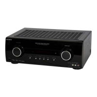
FM STEREO/FM-AM RECEIVER
9-887-542-02
2007C16-1
© 2007.03
Ver. 1.1 2007.03
SPECIFICATIONS
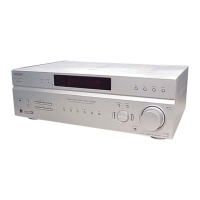
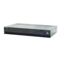
STR-K790
• STR-K790 is the tuner and the amplifier section
in HT-DDW790 and HT-DDW795.
This receiver incorporates Dolby* Digital and Pro Logic Surround and
the DTS** Digital Surround System.
* Manufactured under license from Dolby Laboratories.
“Dolby”, “Pro Logic” and the double-D symbol are trademarks of
Dolby Laboratories.
** “DTS” and “DTS Digital Surround” are registered trademarks of DTS,
Inc.
— Continued on next page —
AUDIO POWER
SPECIFICATIONS
POWER OUTPUT AND TOTAL
HARMONIC DISTORTION:
(Models of area code US only)
With 6 ohm loads, both channels driven, from
120 – 20,000 Hz; rated 85 watts per channel
minimum RMS power, with no more than 1%
total harmonic distortion from 250 milliwatts
to rated output.
Amplifier section
Power Output
1)
Stereo mode (rated) (6 ohms 1 kHz, THD 1%)
85 W + 85 W
Surround mode
2)
(reference)
(6 ohms 1 kHz, THD 10%)
RMS output
FRONT:133 W
per channel
CENTER: 133 W
SURROUND: 133 W
per channel
Surround mode
2)
(reference)
(6 ohms 100 Hz, THD 10%)
SUB WOOFER: 135 W
1)
Measured under the following conditions:
Area code Power requirements
US, Canadian 120 V AC, 60 Hz
AEP, UK 230 V AC, 50 Hz
2)
Reference power output for front, center, surround
speakers and sub woofer. Depending on the sound
field settings and the source, there may be no
sound output.
Inputs
Analog Sensitivity: 800 mV/
50 kohms
Digital (Coaxial) Impedance: 75 ohms
Tone
Gain levels ±6 dB, 1 dB step
Reproduction frequency range:
28 – 20,000 Hz
FM tuner section
Tuning range 87.5 - 108.0 MHz
Antenna FM wire antenna
Antenna terminals 75 ohms, unbalanced
Intermediate frequency
10.7 MHz
AM tuner section
Tuning range
Models of area code US, Canadian
With 10-kHz tuning scale:
530 – 1,710 kHz
4)
With 9-kHz tuning scale:
531 – 1,710 kHz
4)
Models of area code AEP, UK
With 9-kHz tuning scale:
531 – 1,602 kHz
Antenna Loop antenna
Intermediate frequency
450 kHz
4)
You can change the AM tuning scale to 9 kHz or
10 kHz. After tuning in any AM station, turn off
the receiver. While holding down DIMMER, press
?/1. All preset stations will be erased when you
change the tuning scale. To reset the scale to 10
kHz (or 9 kHz), repeat the procedure.
General
Power requirements
Area code Power requirements
US, Canadian 120 V AC, 60 Hz
AEP, UK 230 V AC, 50/60 Hz