34
STR-KS600PM/KS600PW
DIGITAL BOARD IC1301 LC89056W-E (DIGITAL AUDIO INTERFACE RECEIVER)
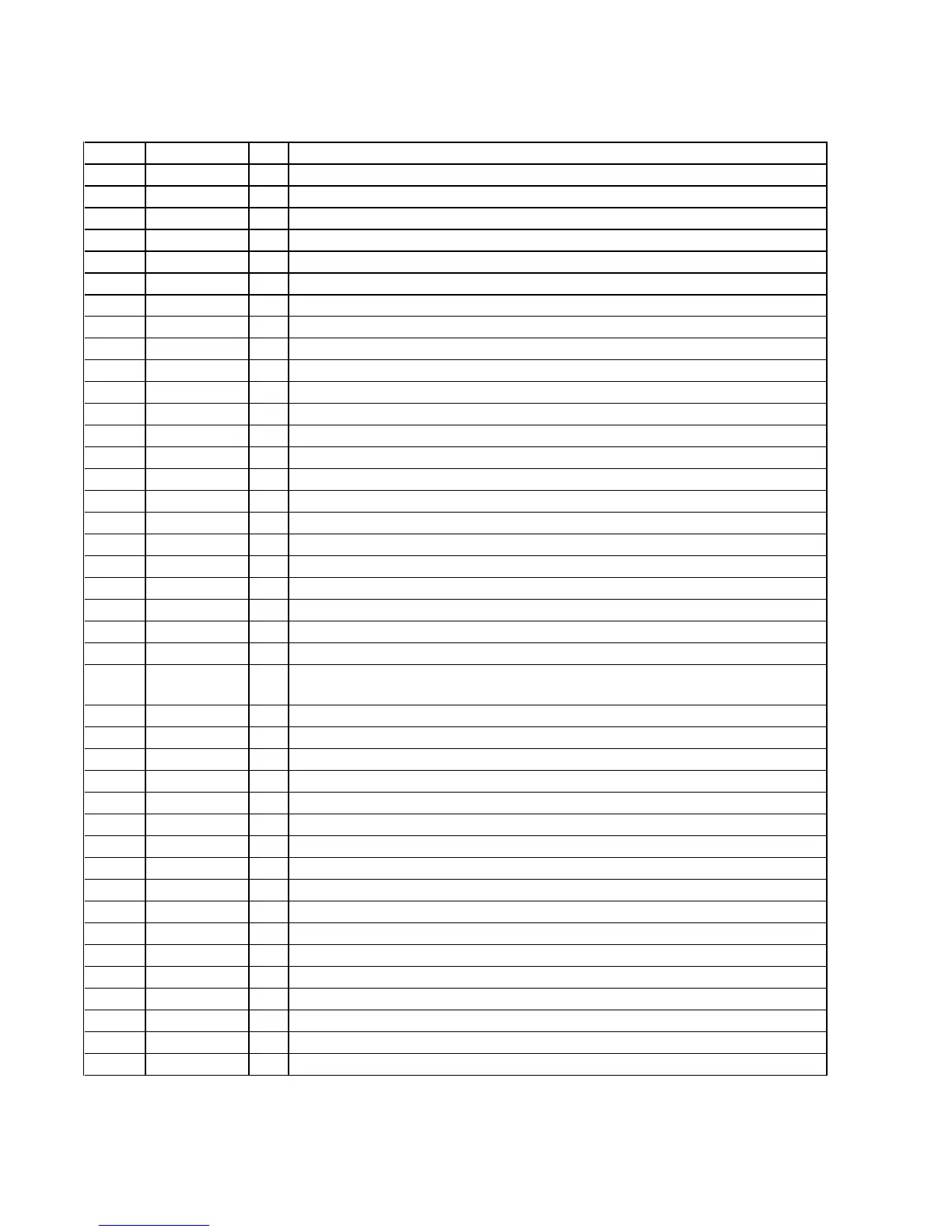
Pin No. Pin Name I/O Description
1
DISEL
I
Selection signal input terminal of data input terminal Fixed at "L" in this set
2
DOUT
O
Digital data output to the external output terminal Not used
3 to 5
DIN0 to DIN2
I
Digital audio signal input terminal
6
D. GND
-
Ground terminal
7
DVDD
-
Power supply terminal (+3.3V)
8
R
I
Input terminal for VCO gain control Not used
9
VIN
I
VCO free-run frequency setting terminal
10
LPF
O
PLL loop filter setting terminal
11
AVDD
-
Power supply terminal (+3.3V)
12
AGND
-
Ground terminal
13
CKOUT
O
Audio clock signal output to the DSP
14
BCK
O
Bit clock signal output to the DSP
15
LRCK
O
L/R sampling clock signal output to the DSP
16
DATAO
O
Audio serial data output to the DSP and system controller
17
XSTATE
O
Source clock selection monitor output to the system controller
18
DGND
-
Ground terminal
19
DVDD
-
Power supply terminal (+3.3V)
20
XMCK
O
System clock signal (12.288 MHz) output to the A/D converter
21
XOUT
O
System clock output terminal (12.288 MHz)
22
XIN
I
System clock input terminal (12.288 MHz)
23
EMPHA
O
Channel status emphasis information output terminal Not used
24
AUDIO
O
Channel status bit 1 output to the DSP
25
CSFLAG
O
Channel status head 40 bit renewal flag output terminal Not used
26 to 29
F0/P0/C0 to
F3/P3/C3
O
Output terminal of input frequency calculation result Not used
30
DVDD
-
Power supply terminal (+3.3V)
31
DGND
-
Ground terminal
32
AUTO
O
Not used
33
BPSYNC
O
Non-PCM burst preamble sync signal output terminal Not used
34
ERROR
O
PLL lock error signal and data error flag output to the DSP and system controller
35
DO
O
Read data output to the system controller
36
DI
I
Write data input from the system controller
37
CE
I
Chip enable signal input from the system controller
38
CLK
I
Clock signal input from the system controller
39
XSEL
I
Selection signal input terminal of crystal oscillator frequency Fixed at "H" in this set
40, 41
MODE0, MODE1
I
Mode setting terminal Fixed at "L" in this set
42
DGND
-
Ground terminal
43
DVDD
-
Power supply terminal (+3.3V)
44, 45
DOSEL0, DOSEL1
I
Output data format selection signal input terminal Fixed at "L" in this set
46
CKSEL0
I
Output clock selection signal input terminal Fixed at "L" in this set
47
CKSEL1
I
Output clock selection signal input terminal Not used
48
XMODE
I
System reset signal input from the system controller "L": reset
• IC Pin Function Description


 To Next Page