Do you have a question about the Sony STR-W777 and is the answer not in the manual?
| Frequency Response | 10Hz to 50kHz |
|---|---|
| Weight | 12.3kg |
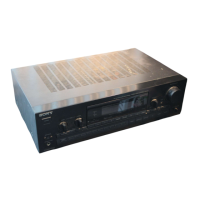
| Type | Receiver |
| Outputs | Composite video, S-Video |
| Tuning range | FM |
Details power output, impedance, and THD for amplifier section.
Covers FM/AM tuner frequency ranges, IF, and aerial specifications.
Includes power requirements, consumption, dimensions, and mass.
Identifies and explains the functions of front panel buttons and dial.
Identifies and explains the functions of rear panel terminals and jacks.
Step-by-step guide for disassembling the sliding panel.
Details MC Cold/Hot Reset, CD Delivery, Sled Servo, and Aging modes.
Explains changing function names and AM tuner step settings.
Covers key check, CD/Tape aging, and panel aging modes.
Details AM/FM tuned level and FM polar adjustments.
Visual guide to the placement of all circuit boards within the unit.
Signal flow block diagrams for sections like the tuner.
Detailed circuit schematics and component layouts for various sections.
Diagrams for integrated circuits and their pin assignments.
Exploded views of the main exterior and sliding panel components.
Exploded views of the front panel, circuit boards, and back panel.
Comprehensive lists of capacitors, resistors, transistors, diodes, and ICs.
Lists of connectors, switches, filters, and other parts.