Do you have a question about the Sony SVE151 Series and is the answer not in the manual?
Follow all labels, stamps, and associated documents for safety during service.
Utilize specified parts with matching safety characteristics for repairs.
Replicate original layout for safety features, wiring, and component placement.
Verify all components and wiring are returned to original condition post-service.
Never reuse components; handle tantalum capacitors carefully due to heat sensitivity.
Use appropriate soldering iron tip temperature and handle patterns with care.
Explains markings like '*', '$', '&' and color variations in the parts list.
Details components and exploded views for the main internal section of the device.
Provides exploded views and part numbers for the Liquid Crystal Display unit.
Lists external accessories such as AC adaptors and power cords with their respective part numbers.
Step-by-step instructions for removing and installing the Central Processing Unit.
| Optical Drive | DVD SuperMulti Drive |
|---|---|
| Wireless | Wi-Fi 802.11b/g/n |
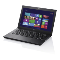
| Series | SVE151 |
| CPU | Intel Core i3/i5/i7 |
| Chipset | Intel HM76 Express |
| Memory | Up to 8GB DDR3 |
| Graphics | Intel HD Graphics 4000 / AMD Radeon HD 7650M |
| Display | 15.5" (1366x768) |
| Storage | 500GB HDD |
| Operating System | Windows 7/8 |
| Bluetooth | Bluetooth 4.0 |
| Webcam | HD Webcam |
| Audio | Built-in stereo speakers, microphone |
| Ports | USB 2.0, USB 3.0, HDMI, VGA, Ethernet, Headphone, Microphone |
| Battery | Lithium-ion battery |
| Weight | 2.7 kg |


