EasyManua.ls Logo

Sony ta-ax44 Service Manual

Sony ta-ax44
36 pages
To Next Page IconTo Next Page
Page #1 background imageLoading...
Page #1 background image
GENERAL
System:
Power Requirements:
Power Consumption:
AC Outlets:
Dimensions:
US
Model
Canadian Model
AEP Model
UK Model
E Model
INTEGRATED STEREO AMPLIFIER
SPECIFICATIONS
Preamplifier section: low-noise IC
equalizer amp.; ASP tone control
Power amplifier section: pure-
complementary SEPP OCL power
amplifier with all stages direct coupled
US, Canadian model: 120 V ac, 60 Hz
AEP model: 220 V ac
(240
V ac adjustable by
authorized Sony personnel),
50/60
Hz
UK model: 240 V ac
(220
V ac adjustable by
authorized Sony personnel),
50/60
Hz
E model: 120, 220 or 240 V ac adjustable,
50160 Hz
US, AEP model: 100 watts
Canadian model: 155 watts
UK model: 270 watts
E model: 100 watts
AEP, UK model: 3 switched, total 100 watts
max.
US, Canadian model:
Two switched (total 100 watts)
One unswitched
(100
watts)
E model: 2 switched, total 100 watts max.
1 unswitched, 100 watts max.
Approx. 430
x
80 x 290 mm (w/h/d)
(I
7
x
31/~
x
11
I/~
inches)
including projecting parts and controls
Weight:
Approx. 5.6 kg (12 Ibs 6 oz) net
Approx. 6 kg (13 lbs 4 oz) in shipping carton
AMPLIFIER SECTION
POWER OUTPUT AND TOTAL HARMONIC
DISTORTION
:
(US, Canadian model)
With 8 ohm loads, both channels driven,
from 20
-
20,000 Hz; rated 40 watts per chan-
nel minimum RMS power, with no more than
0.008% total harmonic distortion from 250
milliwatts to rated output.
-
Continued on page 2
-
SAFETY-RELATED COMPONENT WARNING!!
COMPONENTS IDENTIFIED BY SHADING AND MARK
B
ON THE SCHEMATIC DIAGRAMS, EXPLODED
VIEWS AND IN THE PARTS LIST ARE CRITICAL TO
SAFE OPERATION.
REPLACE THESE COMPONENTS
WITH SONY PARTS WHOSE PART NUMBERS APPEAR
ATTENTION AU COMPOSANT AYANT RAPPORT
AS SHOWN IN THIS MANUAL OR IN SUPPLEMENTS
d.
LA
ScCURITti!
PUBLISHED BY SONY.
LES COMPOSANTS IDENTIFIES PAR UNE TRAME ET
UNE MARQUE
A
SUR LES
DIAGRAMMES
SCHi-
MATIQUES, LES VUES
CCLATiES
ET LA
LISTE
DES
PIiCES
SONT CRITIQUES POUR LA
SliCURITi
DE
FONCTIONNEMENT. NE REMPLACER CES COMPO-
SONY
SANTS QUE PAR DES PICCES SONY DONT LES
NU-
MCROS
SONT
DONNES
DANS CE MANUEL OU DANS
LES
SUPPLeMENTS
PUBLItiS
PAR SONY.
SERVICE MANUAL
Question and Answer IconNeed help?

Do you have a question about the Sony ta-ax44 and is the answer not in the manual?

Sony ta-ax44 Specifications

General IconGeneral
BrandSony
Modelta-ax44
CategoryAmplifier
LanguageEnglish

Summary

Specifications

General Specifications

Details system, power requirements, consumption, outlets, and dimensions.

Amplifier Section Specifications

Details power output and total harmonic distortion for the amplifier section.

Precautions

Safety Precautions

Ensures correct voltage, unplugging, and handling of liquids/objects.

Installation Precautions

Guidance on placement, ventilation, and avoiding heat/dust.

Operation Precautions

Advice on power switch usage, testing, and energy conservation.

Cleaning and Repacking

Instructions for cleaning the unit and repacking it for transport.

Location and Function of Controls

Front Panel Controls

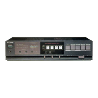
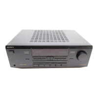
Details the function and location of various switches and buttons on the front panel.

Display Indicators

Explains the fluorescent display and indicator lights for volume, muting, tone, and memory.

Rear Panel Connections

AC Power and Outlets

Explains AC outlet usage, power cord connection, and regional wiring advice.

Input/Output Terminals

Details the various input jacks (Phono, Tuner, AUX, Tape) and speaker outputs.

Operation

Getting Sound

Step-by-step guide on powering on, selecting speakers, and choosing a program source.

Sound Adjustments

Explains how to adjust balance, tone, and use filters (HI-FILTER, SUBSONIC).

Tape Recording and Copy

Recording and Copying Procedures

Instructions for recording audio to tape and copying tapes between recorders.

Remote Control Operation

Section 1 Outline

Block Diagram

Illustrates the functional blocks and signal paths within the amplifier.

Section 2 Disassembly

Top Cover and Bottom Plate

Step-by-step instructions for removing the top cover and bottom plate.

Micon Board

Procedure for disassembling and removing the micon board.

Function Board/Display Board

Steps to remove the function and display boards from the chassis.

Section 3 Diagrams

Power Supply Schematics

Schematics for the power supply section across different regional models.

Control Section Schematic

Detailed schematic of the control section, including function and remote boards.

Audio Section Schematic

Circuit diagram for the input and main boards, detailing audio signal processing.

Mounting Diagrams

Illustrates the physical placement of components on various boards.

Section 4 Exploded Views and Parts List

Main Chassis Exploded View

Diagram showing the breakdown of the main chassis and internal components.

Power Supply Exploded View

Diagram illustrating the assembly of the power supply unit and transformer.

Front Panel Exploded View

Diagram detailing the disassembly and reassembly of the front panel components.

Related product manuals