Do you have a question about the Sony TA-AX350 and is the answer not in the manual?
Details amplifier power output, distortion, and frequency response characteristics.
Lists input sensitivity/impedance and output voltage/impedance details.
Details the frequency bands and gain adjustments for the graphic equalizer.
Critical safety warning for replacing components identified by shading and mark.
Describes the preamplifier and power amplifier circuit types.
Details voltage/frequency requirements and power consumption for different models.
Shows the model number, serial number, and country of manufacture.
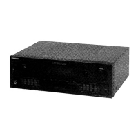
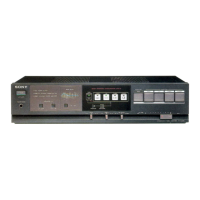
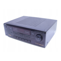
Covers power, volume, balance, headphone jack, and tape indicator functions.
Explains graphic equalizer adjustments and input source selection buttons.
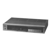
Illustrates and describes rear connections specific to the E model.
Illustrates and describes rear connections for AEP and UK models.
Explains the function of various input (PHONO, TUNER, CD, VIDEO) and output (TAPE RECORDER) jacks.
Covers ground terminal, speaker connectors, AC outlets, voltage selector, and power cord.
Shows the main signal path through L-CH and R-CH amplifier sections.
Illustrates detailed circuit blocks for power, input switching, and control functions.
Instructions and diagrams for removing the front panel of the unit.
Identifies the physical positions of all major circuit boards within the amplifier.
Illustrates component placement on boards and lists semiconductor part numbers and locations.
Details the mounting diagram for the power supply section of the unit.
Provides visual layouts for various semiconductor components used in the device.
Illustrates the physical assembly of the unit with numbered components.
Lists all mechanical and electrical parts with their part numbers and descriptions.
Lists electrical components including capacitors, resistors, semiconductors, ICs, and fuses.
| Type | Integrated Stereo Amplifier |
|---|---|
| Power Output | 40 watts per channel into 8Ω (stereo) |
| Frequency Response | 10Hz to 70kHz |
| Input Sensitivity | 2.5mV (MM), 150mV (line) |
| Signal-to-Noise Ratio | 76dB (MM), 95dB (line) |
| Dimensions | 430 x 135 x 315mm |
| Weight | 8.5 kg |
| Total Harmonic Distortion (THD) | 0.08% |
| Speaker load impedance | 4-16 ohms |