Do you have a question about the Sony TA-A790N and is the answer not in the manual?
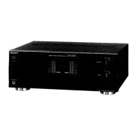
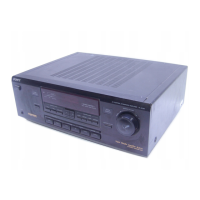
Details model variants, power output, mass, and dimensions of the amplifier.
Highlights critical safety components requiring specific replacement parts.
Provides model-specific voltage/power details and a note for service jig connection.
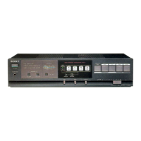
Identifies key components on the front panel using reference numbers.
Step-by-step instructions for disassembling and removing the front panel joint.
Illustrates the placement of various circuit boards within the unit.
Provides pinout diagrams for various transistors, diodes, and ICs used in the unit.
Illustrates the functional blocks and signal paths within the TA-A790N amplifier.
Detailed block diagrams for specific integrated circuits (µPC1237HA, IR2E31A).
Maps specific semiconductor part numbers to their locations on the printed circuit boards.
Visual representations of the printed wiring boards for major sections of the unit.
Explains component notations, abbreviations, and important safety notes for the schematic.
Lists parts and their reference numbers for the front panel assembly.
Lists chassis components, boards, cords, and hardware with reference numbers.
Detailed list of capacitors and jacks for the headphone section.
Comprehensive list of capacitors for the main section of the unit.
Lists capacitors, transistors, diodes, ICs, and resistors for the main circuitry.
Lists components for panel, power switch, and relay sections, including resistors and capacitors.
Lists LEDs, ICs, transistors, and resistors for panel, power switch, and relay sections.
Lists components for relay, sensor, system connector, and transformer secondary boards, plus diodes.
Lists fuses, transistors, resistors, connectors, switches, and transformers for secondary and voltage selection boards.