– 2 –
TABLE OF CONTENTS
1. SERVICING NOTES ................................................ 2
2. GENERAL ................................................................... 3
3. DISASSEMBLY ......................................................... 4
4. DIAGRAMS
4-1. Printed Wiring Boards – MAIN/POWER Section – ..... 7
4-2. Schematic Diagram – MAIN/POWER Section –........... 9
4-3. Schematic Diagram – PANEL Section –....................... 12
4-4. Printed Wiring Boards – PANEL Section – .................. 15
4-5. IC Pin Function Description ........................................... 17
5. EXPLODED VIEWS ................................................ 19
6. ELECTRICAL PARTS LIST ............................... 21
SAFETY-RELATED COMPONENT WARNING!!
COMPONENTS IDENTIFIED BY MARK ! OR DOTTED
LINE WITH MARK ! ON THE SCHEMATIC DIAGRAMS
AND IN THE PARTS LIST ARE CRITICAL TO SAFE
OPERATION. REPLACE THESE COMPONENTS WITH
SONY PARTS WHOSE PART NUMBERS APPEAR AS
SHOWN IN THIS MANUAL OR IN SUPPLEMENTS PUB-
LISHED BY SONY.
SECTION 1
SERVICING NOTES
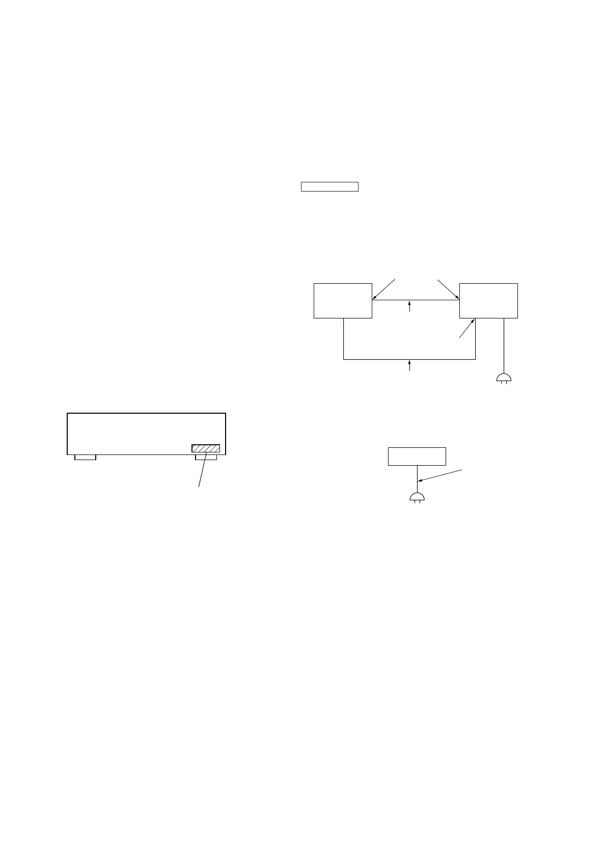
POWER ON/OFF CONTROL
• As the power on/off control is made by the Tuner Unit (ST-
EX880/MS717), the POWER switch is not provided to this set.
Accordingly, for servicing, connect the set to the Tuner Unit
(ST-EX880/MS717). (Fig. 1)
(If the Tuner Unit (ST-EX880/MS717) is not available, connect
a power cord directly to this set. (Fig. 2)
Also, if the set is not connected to the Tuner Unit (ST-EX880/
MS717), to enter the TEST mode (LED CHECK mode), press
FUNCTION v button and [SOURCEDIRECT] button simul-
taneously two times.
When each button is pressed, the LED associated with each but-
ton lights up.
Connection:
Set
Tuner Unit
(ST-EX880/
MS717)
AC IN
Connector cable
(17P)
AC IN
terminal
Power cord attached to this set
SYSTEM CONTROL
terminal
Fig. 1
Fig. 2
4-995-104-1
π
: AEP, UK
4-995-104-2
π
: Hong Kong, Singapore, Malaysia
4-995-104-3
π
: Tourist
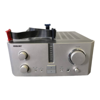
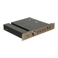
MODEL IDENTIFICATION
– Back panel –