EasyManua.ls Logo

Sony ta-f730es Service Manual

Sony ta-f730es
17 pages
To Next Page IconTo Next Page
Page #1 background imageLoading...
Page #1 background image
Continuous
RMS
power
outut
(both
channels
driven
simultaneously)
Power
band
width
(IHF)
Dynamic
headroom
('78
IHF)
photo:
TA-F730ES
SPECIFICATIONS
Condition
4
ohms,
20
Hz-20
kHz
THD
0.008%
6
ohms,
20
Hz-20
kHz
THD
0.006%
UK,
E,
WG
model
UK,
E,
WG
model
AEP
model
8
ohms,
20
Hz-20
kHz
THD
0.004%
UK,
E,
WG
model
AEP
model
8
ohms,
THD
0,02%
8
ohms
REVISED
Data
145
W
+
145
W
(THD
0.008%)
(DIN:
185
W
+
185
W)
125
W
+
125
W
(DIN:
150
W +
150
W)
120
W
+
120
W
(DIN:
140
W
+
140
W)
110W+
110
W
(DIN:
130
W +
130
W)
105
W
+
105
W
(DIN:
115
W
+
115
W)
10
Hz
-
100
kHz
at
50
W
2
dB
Total
harmonic
distortion
8
ohms,
at
10
watt
output
0.002%
Intermodulation
(1M)
distortion
60
Hz:
7
kHz
=
4:1
Damping
factor
Residual
noise
Frequency
response
Input
sensitivity
—Continued
on
page
4
ohm,
at
rated
output
6
ohms
at
rated
output
0.008%
0.006%
TUNER,
CD,
TAPE
1,
2,
3,
DIRECT
IN
TUNER,
CD,
DIRECT
IN,
TAPE
1,
2,3
ADAPTOR
IN
2-
2Hz-200kHz
*3
dB
0.17
mV,
100
ohms
2.5
mV,
50
kohms
150
mV,
50
kohms
AEP
Model
UK
Model
TA
-F730ES
E
Model
TA
-F333ESR
INTEGRATED
STEREO
AMPLIFIER
SONY.

Other manuals for Sony ta-f730es

Question and Answer IconNeed help?

Do you have a question about the Sony ta-f730es and is the answer not in the manual?

Sony ta-f730es Specifications

General IconGeneral
BrandSony
Modelta-f730es
CategoryAmplifier
LanguageEnglish

Summary

Model Identification

Block Diagram

Section 1 General

Function of Controls Overview

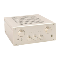
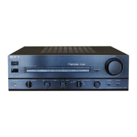
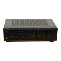
Details the operation and purpose of each control knob, switch, and selector on the unit.

Section 2 Disassembly

Component Disassembly Procedures

Covers disassembly of main board, case, front panel, and back panel assemblies.

Section 3 Switch Block Removal

Switch Block Removal and Attachment Guide

Step-by-step instructions for safely removing and attaching the switch block.

Section 4 Electrical Adjustments

Offset and Bias Adjustment Procedures

Detailed steps for performing offset and bias adjustments using a voltmeter.

Section 5 Diagrams

Semiconductor Layouts and Circuit Board Locations

Visual references for semiconductor pinouts and the physical locations of circuit boards.

Section 6 Exploded Views

Case Assembly Exploded View and Parts List

Detailed exploded view of the case assembly, identifying individual parts and their numbers.

Section 7 Electrical Parts List

Capacitor, Resistor, and Semiconductor Parts

Comprehensive list of capacitors, resistors, and semiconductor components with part numbers and specifications.

Related product manuals