EasyManua.ls Logo

Sony TA-F3000 Service Manual

Sony TA-F3000
16 pages
To Next Page IconTo Next Page
Page #1 background imageLoading...
Page #1 background image
— 1 —
SERVICE MANUAL
AEP Model
UK Model
TA-F3000ES
E Model
Chinese Model
TA-F3000
TA-F3000/F3000ES
SPECIFICATIONS
Photo: TA-F3000
INTEGRATED STEREO AMPLIFIER
MICROFILM
w
w
w
.
x
i
a
o
y
u
1
6
3
.
c
o
m
Q
Q
3
7
6
3
1
5
1
5
0
9
9
2
8
9
4
2
9
8
T
E
L
1
3
9
4
2
2
9
6
5
1
3
9
9
2
8
9
4
2
9
8
0
5
1
5
1
3
6
7
3
Q
Q
TEL 13942296513 QQ 376315150 892498299
http://www.xiaoyu163.com
Question and Answer IconNeed help?

Do you have a question about the Sony TA-F3000 and is the answer not in the manual?

Sony TA-F3000 Specifications

General IconGeneral
BrandSony
ModelTA-F3000
CategoryAmplifier
LanguageEnglish

Summary

Specifications

General

Front and Rear Panel Descriptions

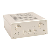
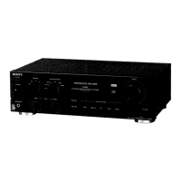
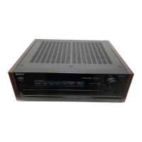
Detailed identification of front and rear panel controls, connectors, and indicators.

Electrical Adjustments

Bias Adjustment

Procedure for adjusting the amplifier's bias for optimal performance and stability.

Diagrams

Circuit Boards Location

Diagram showing the physical layout and interconnections of various circuit boards within the unit.

Schematic Diagram - Main Section

Detailed schematic illustrating the main audio processing and amplification circuitry of the device.

Printed Wiring Board - Main Section

Layout of the main circuit board, showing component placement and traces for assembly and repair.

Schematic Diagram - Panel Section

Schematic diagram of the front panel controls, indicators, and associated circuitry.

Printed Wiring Board - Panel Section

Component layout for the panel section, detailing the arrangement of parts on its printed circuit board.

IC Block Diagrams

High-level block diagrams illustrating the internal logic and function of integrated circuits used in the unit.

IC Pin Function

Detailed pin assignments and functions for key integrated circuits, crucial for troubleshooting and analysis.

Exploded Views

Front Panel Section

Exploded view illustrating the assembly of the front panel components and their order.

Chassis Section

Exploded view detailing the assembly of the main chassis, internal chassis components, and mounting hardware.

Electrical Parts List

Related product manuals