EasyManua.ls Logo

Sony ta-f333esr Service Manual

Sony ta-f333esr
17 pages
To Next Page IconTo Next Page
Page #1 background imageLoading...
Page #1 background image
Continuous
RMS
power
outut
(both
channels
driven
simultaneously)
Power
band
width
(IHF)
Dynamic
headroom
('78
IHF)
photo:
TA-F730ES
SPECIFICATIONS
Condition
4
ohms,
20
Hz-20
kHz
THD
0.008%
6
ohms,
20
Hz-20
kHz
THD
0.006%
UK,
E,
WG
model
UK,
E,
WG
model
AEP
model
8
ohms,
20
Hz-20
kHz
THD
0.004%
UK,
E,
WG
model
AEP
model
8
ohms,
THD
0,02%
8
ohms
REVISED
Data
145
W
+
145
W
(THD
0.008%)
(DIN:
185
W
+
185
W)
125
W
+
125
W
(DIN:
150
W +
150
W)
120
W
+
120
W
(DIN:
140
W
+
140
W)
110W+
110
W
(DIN:
130
W +
130
W)
105
W
+
105
W
(DIN:
115
W
+
115
W)
10
Hz
-
100
kHz
at
50
W
2
dB
Total
harmonic
distortion
8
ohms,
at
10
watt
output
0.002%
Intermodulation
(1M)
distortion
60
Hz:
7
kHz
=
4:1
Damping
factor
Residual
noise
Frequency
response
Input
sensitivity
—Continued
on
page
4
ohm,
at
rated
output
6
ohms
at
rated
output
0.008%
0.006%
TUNER,
CD,
TAPE
1,
2,
3,
DIRECT
IN
TUNER,
CD,
DIRECT
IN,
TAPE
1,
2,3
ADAPTOR
IN
2-
2Hz-200kHz
*3
dB
0.17
mV,
100
ohms
2.5
mV,
50
kohms
150
mV,
50
kohms
AEP
Model
UK
Model
TA
-F730ES
E
Model
TA
-F333ESR
INTEGRATED
STEREO
AMPLIFIER
SONY.

Other manuals for Sony ta-f333esr

Question and Answer IconNeed help?

Do you have a question about the Sony ta-f333esr and is the answer not in the manual?

Sony ta-f333esr Specifications

General IconGeneral
TypeIntegrated Stereo Amplifier
Speaker Load Impedance4 - 16 ohms
Frequency Response5Hz-100kHz
Total Harmonic Distortion (THD)0.008%
Input Sensitivity150 mV (line in)
Damping Factor100
Dimensions430 x 150 x 400 mm (W x H x D)
Signal-to-Noise Ratio110dB (IHF-A)

Summary

Amplifier Specifications

General Specifications and Model Details

Details on system, power, dimensions, weight, and model identification for regional variants.

General Information and Controls

Function of Controls

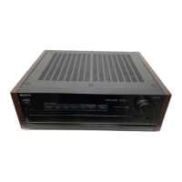
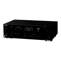
Explanation of the amplifier's front panel controls and their operational functions.

Disassembly Procedures

Component Disassembly Guide

Instructions for disassembling main boards, EQ MA board, and capacitor holder.

Removal Switch Block

Switch Block Removal and Attachment Procedure

Procedure for removing and attaching the switch block mechanism.

Electrical Adjustments

Offset and Bias Adjustment Procedures

Guides for adjusting offset voltage to zero and bias current to 15mV.

Technical Diagrams

Semiconductor Layouts and Circuit Board Locations

Semiconductor lead layouts and diagram showing circuit board locations.

Exploded Views

Case Assembly Exploded View

Detailed breakdown of the amplifier's case assembly components.

Front and Back Panel Assemblies Exploded View

Exploded view of the front and back panel assemblies.

Main Chassis Assembly Exploded View

Detailed breakdown of the amplifier's main chassis assembly components.

Electrical Parts List

Related product manuals