Do you have a question about the Sony TA-F45 and is the answer not in the manual?
Details the AC voltage and frequency requirements for different models.
Specifies the power wattage consumed by the unit for various models.
Describes the types and ratings of AC outlets on the unit.
Provides the physical size of the amplifier in mm and inches.
Lists the net and shipping weight of the amplifier.
Critical components for safe operation must be replaced with specified SONY parts.
Caution regarding shock hazard when servicing the switching-type power supply circuit.
Details power output ratings and total harmonic distortion for the amplifier.
Specifies continuous RMS power output with low THD for different load conditions.
Indicates the frequency range over which power is delivered with specified distortion.
Lists harmonic distortion levels at rated output and at 25W.
Reports intermodulation distortion levels at rated output and at 25W.
Details the frequency response for PHONO, TUNER, and AUX inputs.
Specifies the residual noise level when no signal is input.
Indicates the damping factor for speaker output.
Lists the available input types, sensitivity, and impedance.
Details the voltage and impedance of the output terminals.
Describes the adjustment range and turnover frequencies for bass and treble controls.
Specifies the boost levels for loudness compensation at different frequencies.
Describes the low-frequency attenuation characteristics.
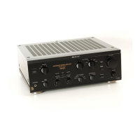
Shows details from the unit's specification label, including model and power ratings.
Step-by-step guide for removing the top cover and bottom plate.
Instructions for disassembling and removing the front panel.
Procedure for adjusting DC bias for L-CH and R-CH.
Procedure for adjusting DC balance to OV for L-CH and R-CH.
Illustrates the physical layout and mounting of components on circuit boards.
Detailed circuit schematics for various sections of the amplifier.
Illustrated parts breakdown showing component placement and assembly for main unit.
Further illustrations of component placement and assembly for chassis and related parts.
Detailed exploded view of the pulse power supply unit and its components.
Exploded views of internal components like fuses, relays, and switches.
List of transistors, diodes, and ICs used in the amplifier.
Comprehensive list of capacitors, including types and ratings.
List of all resistors used, including wattage and resistance values.
Includes items like fuses, jacks, switches, and relays not categorized elsewhere.
Lists items like bags, manuals, cushions, and cartons.
Identifies the part numbers for various printed circuit boards.
| Power Output | 60 watts per channel into 8Ω (stereo) |
|---|---|
| Frequency Response | 7Hz to 100kHz |
| Input Sensitivity | 0.17mV (MC), 2.5mV (MM), 150mV (line) |
| Signal to noise ratio | 76dB (MC), 95dB (MM), 103dB (line) |
| Dimensions | 430 x 135 x 315mm |
| Weight | 8.2kg |
| Type | Integrated amplifier |
| Total Harmonic Distortion (THD) | 0.008% |
| Speaker Impedance | 4Ω to 16Ω |