Do you have a question about the Sony TA-F120A and is the answer not in the manual?
Describes RMS power output for both channels driven simultaneously under various conditions.
Details REC OUT, SPEAKERS, and HEADPHONES output jack types and impedance.
Details input jack types, sensitivity, and impedance for various audio sources.
Describes the BASS, TREBLE, and Loudness control functions and their response.
Refers to the label on the unit detailing model, serial number, and voltage specifications.
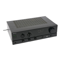
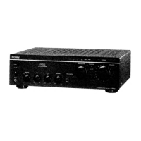
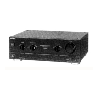
Lists and identifies various external and internal components of the amplifier.
Provides instructions and diagrams for connecting external audio devices and speakers.
Details how to adjust bias current for optimal performance using a VOM.
Illustrates the physical arrangement and numbering of circuit boards within the unit.
Shows the pin configurations for key semiconductors used in the amplifier.
Illustrates the internal functional blocks of integrated circuits used in the amplifier.
Displays the copper traces and component placement on printed circuit boards.
Provides detailed electrical circuit schematics for the amplifier's various sections.
Shows the exploded view of the front panel components and their part numbers.
Displays the exploded view of the amplifier's chassis components and their part numbers.
Lists all electrical components with part numbers, descriptions, and specifications.
Lists included instruction manuals in multiple languages and packaging materials.
| Power Output | 20W per channel (8 ohms, 20Hz-20kHz, 0.1% THD) |
|---|---|
| Frequency Response | 7 Hz to 100 kHz +0 dB/-3 dB |
| Signal-to-Noise Ratio | 90dB (MM), 100dB (Line) |
| Dimensions | 430 x 125 x 310 mm (W x H x D) |
| Weight | 7.5 kg |
| Total harmonic distortion | 0.1% (20Hz-20kHz, 8 ohms) |
| Input sensitivity (MM) | 2.5 mV |
| Input sensitivity (Line) | 150 mV |
| Signal to noise ratio (MM) | 90 dB |
| Signal to noise ratio (Line) | 100 dB |
| Speaker load impedance | 4 to 16 ohms |
| Input Sensitivity | 2.5mV (MM), 150mV (Line) |
| Input Impedance | 47k ohms (line) |