Do you have a question about the Sony TA-F100 and is the answer not in the manual?
Continuous RMS power output (both channels driven simultaneously).
RMS power output for different impedance and frequency ranges.
Critical warning regarding safety-related components.
Provides solutions for common operational problems.
Detailed circuit schematic for the amplifier.
Comprehensive list of electrical components with part numbers and specifications.
| Frequency Response | 10Hz to 70kHz |
|---|---|
| Input sensitivity | 2mV (MM), 150mV (line) |
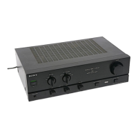
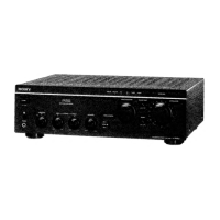
| Type | Integrated Amplifier |
| Total Harmonic Distortion (THD) | 0.05% |
| Signal-to-Noise Ratio | 100dB (IHF-A) |
| Inputs | phono, tuner, aux, tape |
| Speaker load impedance | 8Ω to 16Ω |