EasyManua.ls Logo

Sony TA-F442E User Manual

Sony TA-F442E
16 pages
To Next Page IconTo Next Page
Page #1 background imageLoading...
Page #1 background image
TA-F442E/FO42E
SERVICE
MANUAL
UK
Model
Photo
:
TA-F542E
SPECIFICATIONS
Amplifier
Continuous
RMS
power
output
(both
channels
driven
simultaneously)
TA-F442E
|
TA-F542E
|
4ohms
_|110
W
+
110
W/120
W
+
120
W
8ohms
|
90W
+
90W
1100
W
+
100
W
20
Hz
-
20
KHz
THD
0.008
%
8
ohms
|
80
W
+
80W
|
90W
+
90
W
Input
DIN
1
kHz
:
__|S/N
(weighting
-
Jack
type|
Sensitivity
|
mpedance!
network,
input
ae
~s
Hevel)
oo
Input
jack
MM
2.0mV_
[50
kilohms|
94
dB
(A,
5
mV)
I
SADE)
es
0.25.
mV
|100
ohms
|
76
dB(A,
0.5
mV)
TUNER,
CD,
AUX,
TAPE1,
DAT/TAPE2
150
mV_
|
50
kilohms
}100
dB
(150
mV)
Output
Voltage/impedance
Voltage
150
mV
Impedance
1
kilohm
4-16
ohms
(A
or
B)
8-16
ohms
(A
+
B)
HEADPHONES
|
Stereo
phone
|
Accepts
low
and
high
jack
impedance
headphones.
Output
jack
Jack
type
REC
OUT
Phono
SPEAKERS
Intermodulation
(IM)
distortion
(60
Hz:7
KHz
=
4:1)
Less
than
0.008
%
at
rated
output
PHONO:
RIAA
equalization
curve
+0.5
dB
TUNER,
CD,
AUX,
TAPE1,
TAPE2/DAT:
5
Hz
-
120
kHz
+3
dB
Less
than
170
nV,
(network
A)
70
(8
ohms,
1
KHz)
Frequency
response
Residual
noise
Damping
factor
Continued
on
page
2
INTEGRATED
STEREO
AMPLIFIER
SON
Y.
Question and Answer IconNeed help?

Do you have a question about the Sony TA-F442E and is the answer not in the manual?

Sony TA-F442E Specifications

General IconGeneral
BrandSony
ModelTA-F442E
CategoryAmplifier
LanguageEnglish

Summary

Section 1: General

1-1. Connections

Details on connecting external audio equipment to the amplifier for proper operation.

1-2. Parts Identification

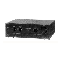
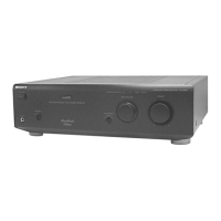
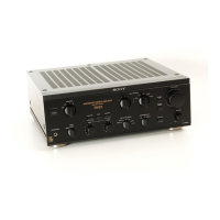
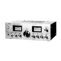
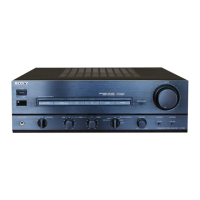
Identification of front panel controls, switches, and connectors for user interaction.

Section 2: Disassembly

2-1. Disassembling for Board Check

Procedure for removing the front panel to access the HP/LED board for inspection or maintenance.

Section 3: Electrical Adjustments

DC Bias Adjustment

Procedure to adjust bias voltage on the main board, critical after power amplifier transistor replacement.

Section 4: Diagrams

4-1. Block Diagram

Visual representation of the amplifier's signal path and functional blocks for system overview.

4-2. Circuit Boards Location

Diagram illustrating the physical placement of internal circuit boards within the unit.

4-3. Printed Wiring Boards

Layouts of the printed wiring boards for key internal sections like MAIN, SP, and INPUT.

4-4. Schematic Diagram

Detailed electrical schematic diagram of the amplifier's circuitry for in-depth analysis.

Section 5: Exploded Views

5-1. Case, Front Panel

Exploded view and parts list for the amplifier's case and front panel assembly.

5-2. Chassis, Back Panel

Exploded view and parts list for the amplifier's chassis and back panel components.

Section 6: Electrical Parts List

Capacitors

List of all capacitors used in the amplifier, including part numbers and specifications.

Semiconductors

List of semiconductors (transistors, diodes, ICs) with their respective part numbers.

Diodes

Details on diodes used, providing part numbers, types, and electrical characteristics.

ICs and Connectors

List of integrated circuits, connectors, and associated part numbers for reference.

Transistors

Comprehensive list of transistors, detailing part numbers and types for various circuit sections.

Resistors

List of resistors, including part numbers, values, tolerance, and power rating.

Variable Resistors and Relays

Listing of variable resistors (potentiometers) and relays with their corresponding part numbers.

Switches and Jacks

List of switches, slide switches, and input/output jacks with their respective part numbers.

Miscellaneous Parts

List of miscellaneous components such as cords, fuses, and transformers.

Hardware List

Inventory of screws and hardware used in the assembly and maintenance of the unit.

Related product manuals