EasyManua.ls Logo

Sony TA-FA5ES Service Manual

Sony TA-FA5ES
30 pages
To Next Page IconTo Next Page
Page #1 background imageLoading...
Page #1 background image
TA-FASES/FA7ES
SERVICE
MANUAL
Photo:
TA-FA7ES
(Black)
AEP
Model
System
SPECIFICATIONS
Power
Amplifier:
Pure-complementary
SEPP
MOS
FET
power
amplifier
with
all
stages
directly
coupled
Preamplifier:
Low-noise,
high-gain
equalizer
amplifier
Power
section:
Large-capacity
power
supply
advanced
STD
Rated
output
Speakers
impedance
Output
bandwidth
(8
ohms)
Dynamic
headroom
Total
harmonic
distortion
Damping
factor
Intermodulation
(IM)
distortion
(60
Hz:7
kHz=4:1)
Throughrate
Residual
noise
Equalizer
deviation
Frequency
response
S/N
TA-FA7ES
4
ohms,
150
W
+
150
W
(DIN
0.7%)
8
ohms,
100
W
+
100
W
(DIN
0.7%)
TA-FA5ES
4
ohms,
135
W
+
135
W
(DIN
0.7%)
8
ohms,
90
W
+
90
W
(DIN
0.7%)
4
to
16
ohms
;
10
Hz
to
100
kHz
(at
40
W
output,
and
high-frequency
distortion
rate
of
0.08%)
at
4
ohms:
TA-FA7ES
2
dB
TA-FASES
3
dB
at
8
ohms:
TA-FA7ES
1.2
dB
TA-FA5ES
2
dB
0.005%
(at
8
ohms,
10
W
output)
100
(8
ohms,
1
kHz)
0.005%
(8
ohms)
125
V/p
sec,
250
V/U
sec
(Inside)
Less
than
115
1.
V
(network
A)
PHONO
MM:
20
Hz
to
20
kHz,
+0.2
dB
TUNER,
CD,
AUX,
TAPE
1,
2,
3:
2
Hz
to
100
kHz
*$dB
PHONO
MC:
TA-FA7ES
78dB
(A
Fil,
0.5
mV)
TA-FASES
76
dB
(A
Fil,
0.5
mV)
MM:
87
dB
(A
Fil,
5
mV)
TUNER,
CD,
AUX,
TAPE,
2,
3:
105
dB
Inputs
Input
sensitivity
and
impedance
Maximum
input
capability
(1
kHz)
Outputs
Output
level
/
impedance
Tone
controls
General
Power
requirements
Power
consumption
PHONO
MC:
0.25
mV,
100
ohms
MM:
2.5
mV,
50
kilohms
TUNER,
CD,
AUX,
TAPE
1,
2,
3:
150
mV,
30
kilohms
PHONO
MC:
9
mV
MM:
150
mV
REC
OUT
1,
2,3:
150
mV,1
kilohms
PHONES:
10
mW
(at
8
ohms)
BASS
(100
Hz):
+7
dB
TREBLE
(10
kHz):
+6
dB
220
-
230
V
AC,
50/60
Hz
TA-FA7ES:
330
W
TA-FA5ES:
300
W
Dimensions
(approx.)
(w/h/d)
430
x
175
x
450
mm
Mass
(approx.)
Supplied
accessories
(17
x
7x
173/,
inches)
incl.
projecting
parts
and
controls
TA-FA7ES:
19.8
kg
(43
lb
6
oz)
TA-FASES:
17.5
kg
(38
Ib
10
oz)
Remote
commander
(remote)
RM-S703
(1)
Sony
batteries
SUM-3(NS)
(2)
Design
and
specifications
are
subject
to
change
without
notice.
INTEGRATED
STEREO
AMPLIFIER
SON
Y.
Question and Answer IconNeed help?

Do you have a question about the Sony TA-FA5ES and is the answer not in the manual?

Sony TA-FA5ES Specifications

General IconGeneral
BrandSony
ModelTA-FA5ES
CategoryAmplifier
LanguageEnglish

Summary

Specifications

System Specifications

Detailed technical specifications for the amplifier's system components.

Input and Output Specifications

Specifications for input sensitivity, impedance, output levels, and connections.

Tone Controls and General Data

Details on tone control ranges and general unit specifications like power and dimensions.

General Information and Controls

Front Panel Control Layout

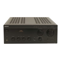
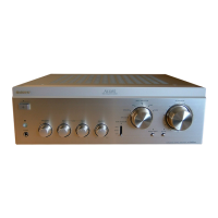
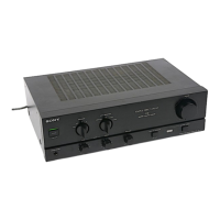
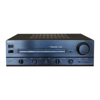
Diagram and description of the front panel controls and indicators.

Rear Panel Connections

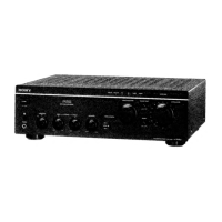
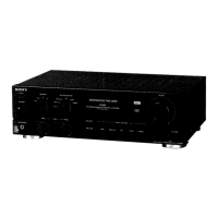
Identification and description of rear panel input/output and connection terminals.

Disassembly Procedures

Cabinet Panel Removal

Step-by-step guide for removing external cabinet panels and covers.

Internal Board Removal

Procedure for safely removing internal circuit boards.

Internal Component Disassembly

Disassembly of Control and Power Boards

Instructions for disassembling AC SW, Tone Control, and Volume boards.

Disassembly of Power Supply and Associated Boards

Procedure for removing power supply and related circuit boards.

Further Disassembly Steps

Disassembly of Connectivity and Input Boards

Guide for removing I/O, SP-TM, Jumper, and Input boards.

Disassembly of Main, Pre-PS, and Balance Boards

Instructions for disassembling Main, Pre-PS, and Balance boards.

Electrical Adjustment Procedures

Bias Adjustment Procedure

Detailed steps for performing the bias adjustment on the amplifier's boards.

Diagrams and IC Information

IC Pin Function Description

Description of the pin functions for the System Control IC (IC901).

Circuit Board Layouts

Circuit Board Location Overview

Visual guide showing the physical location of all major circuit boards within the unit.

Integrated Circuit Diagrams

IC Block Diagrams

Block diagrams illustrating the internal functions of key integrated circuits.

Schematic Diagrams

Printed Wiring Board Layouts

Main Section Layouts

Printed wiring board diagrams for the main sections of the amplifier.

Printed Wiring Board Layouts (Control)

Control Section Layouts

Printed wiring board diagrams for the control sections of the amplifier.

Exploded Views

Cabinet Section Exploded View

Exploded view illustrating the assembly of the amplifier's cabinet and external parts.

Exploded Views (Components)

Front Panel Section Exploded View

Exploded view detailing the components and assembly of the front panel.

Chassis and Internal Exploded Views

Chassis Section Exploded View

Exploded view showing the chassis and internal component mounting.

Back Panel Exploded Views

Back Panel Section Exploded View

Exploded view illustrating the assembly of the amplifier's back panel and connections.

Electrical Parts List

AC SW, Balance, and Function LED Parts

List of electrical components for the AC SW, Balance, and Function LED boards.

Electrical Parts List (Continued)

Function LED, HP, and Input Parts

List of electrical components for the Function LED, HP, and Input boards.

Electrical Parts List (Components)

Input, Jumper, and Main A Parts

List of electrical components for the Input, Jumper, and Main A boards.

Electrical Parts List (Main A)

Main A Board Parts

Detailed list of components for the Main A board.

Electrical Parts List (Main Boards)

Main A and Main B-L Board Parts

List of components for the Main A and Main B-L boards.

Electrical Parts List (Various Boards)

Main B-L, B-R, Medama, Mut LED, Out Let Parts

Component list for Main B-L, B-R, Medama, Mut LED, and Out Let boards.

Electrical Parts List (More Boards)

Out Let, Pre PS, and Pro Parts

Component list for Out Let, Pre PS, and Pro boards.

Electrical Parts List (Final Boards)

Pro, Pro LED, and PS Parts

Component list for Pro, Pro LED, and PS boards.

Electrical Parts List (Specialized Boards)

PS, PS Jumper, Rec Out, SP-TM, Tone Control Parts

Component list for PS, Jumper, Rec Out, SP-TM, Tone Control boards.

Electrical Parts List (Control and Volume)

Tone Control and Volume Parts

Component list for Tone Control and Volume boards.

Electrical Parts List (Volume Section)

Volume Control Parts

Component list specifically for the Volume control section.

Service Manual Corrections

Electrical Adjustment Correction

Correction notice for the bias adjustment procedure on page 7.

Related product manuals