Do you have a question about the Sony TA-F444ESX and is the answer not in the manual?
Details of power output and total harmonic distortion.
Lists power consumption and details AC outlets for different models.
Physical dimensions and net weight of the amplifier.
Describes the "Gibraltar" head chassis for rigidity and damping.
Explains the use of large capacity capacitors for stable power.
Discusses passive tone controls and the source direct function.
Describes the system for powerful reproduction without distortion.
Procedures to ensure safe operation after service.
Detailed procedure for testing AC leakage from metal parts to earth ground.
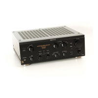
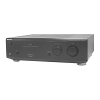
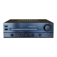
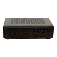
Identifies and describes controls and indicators on the front panel.
Identifies and describes input/output jacks and terminals on the rear panel.
Details power, speaker, input, muting, mode, and tone controls.
Covers bass, treble, subsonic filter, balance, REC OUT, and cartridge load selectors.
Describes audio inputs, adaptor jacks, AC outlets, and grounding.
Illustrates the main signal paths and component interconnections.
Visual guide showing component placement on circuit boards.
Diagrams illustrating the pin configurations of various semiconductors.
Diagram showing the physical location of various circuit boards within the unit.
Illustrates the internal functions of the integrated circuits.
Step-by-step guide for removing the top cover and bottom plate.
Instructions for detaching the front panel and jack plate assemblies.
Illustrates mechanical components with part numbers.
Lists all electrical components with part numbers and specifications.