EasyManua.ls Logo

Sony TA-FLX9W User Manual

Sony TA-FLX9W
26 pages
To Next Page IconTo Next Page
Page #1 background imageLoading...
Page #1 background image
SERVICE MANUAL
Power ouput 40 watts/ch
(6 ohms at 1 kHz, 0.7%
THD)
2)
60 watts/ch
1)
(6 ohms at 1 kHz, 10%
THD)
2)
1)
Depending on the sound field settings and the source,
there may be no sound output.
2)
Measured under AC 127, 240 V, 50/60 Hz
(Saudi Arabian model only)
Measured under AC 120, 240 V, 50/60 Hz
(except for Saudi Arabian model)
G
Amplifier section:
eneral
Power requirements
Saudi Arabian model: 120 – 127 V or 220 – 240 V
AC, 50/60 Hz
Adjustable with voltage
selector
Thailand model: 220 – 240 V AC, 50/60 Hz
Other models: 110 – 120 V or 220 – 240 V
AC, 50/60 Hz
Adjustable with voltage
selector
Power consumption
92 watts
Dimensions (w/h/d)
Approx. 95 × 156 ×
241 mm
Mass
Approx. 3.1 kg
Design and specifications are subject to change
without notice.
REAR AMPLIFIER
E Model
SPECIFICATIONS
TA-FLX9W
Ver 1.0 2004.07
9-877-903-01
2004G05-1
© 2004.07
Sony Corporation
Home Audio Company
Published by Sony Engineering Corporation
TA-FLX9W is the amplifier section in DHC-FLX9W.
w
w
w
.
x
i
a
o
y
u
1
6
3
.
c
o
m
Q
Q
3
7
6
3
1
5
1
5
0
9
9
2
8
9
4
2
9
8
T
E
L
1
3
9
4
2
2
9
6
5
1
3
9
9
2
8
9
4
2
9
8
0
5
1
5
1
3
6
7
3
Q
Q
TEL 13942296513 QQ 376315150 892498299
http://www.xiaoyu163.com
Question and Answer IconNeed help?

Do you have a question about the Sony TA-FLX9W and is the answer not in the manual?

Sony TA-FLX9W Specifications

General IconGeneral
BrandSony
ModelTA-FLX9W
CategoryAmplifier
LanguageEnglish

Summary

Service Manual Overview

Specifications

Details amplifier output power, power requirements, consumption, dimensions, and mass.

Component Replacement Notes

Unleaded Solder Handling

Explains characteristics and handling of unleaded solder for component replacement.

Safety Component Warning

General Information

Location of Controls

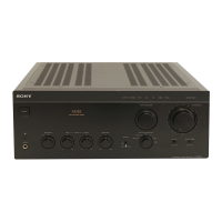
Identifies and locates the controls on the front panel of the unit.

Disassembly Procedures

Disassembly Flowchart

Outlines the step-by-step procedure for disassembling the set in numerical order.

Removing the Rear Amplifier Case

Details the procedure for removing the rear amplifier case, including screw locations.

Removing the VS Board

Explains how to remove the VS board, showing connector and screw locations.

Removing the RX Board

Details the removal of the RX board, indicating screw and wire connections.

Removing the Main Board

Describes the process for removing the MAIN board, listing connector and screw details.

System Diagrams

Block Diagram Overview

Presents a block diagram illustrating the overall system architecture and signal flow.

Diagram Interpretation Notes

Printed Wiring Board Notes

Provides notes on interpreting printed wiring board diagrams, including symbols for parts.

Schematic Diagram Conventions

Explains conventions and symbols used in schematic diagrams for components and lines.

RX Board Waveform Details

Details waveform characteristics and measurement notes for the RX Board.

RX Board Printed Wiring

Semiconductor Locations on RX Board

Lists semiconductor component reference numbers and their locations on the RX board.

RX Board Schematic (Part 1)

RX Board Schematic (Part 2)

Main Board Printed Wiring

Semiconductor Locations on Main Board

Lists semiconductor component reference numbers and their locations on the MAIN board.

Power Supply Boards Printed Wiring

Semiconductor Locations on PSU Boards

Lists semiconductor component reference numbers and their locations on the STBY, VS, and PSW boards.

Main Board Schematic

Integrated Circuit Block Diagrams

IC7401, IC7404, IC7402 Block Diagrams

Displays block diagrams for IC7401, IC7404, and IC7402 detailing their internal functions.

Audio IC Block Diagrams

IC7407, IC7409 Block Diagrams

Shows block diagrams for IC7407 and IC7409, illustrating their internal structures and signals.

IC Pin Function Descriptions

IC7405 Rear Amp Controller Pinout

Lists pin numbers, names, I/O, and descriptions for IC7405, the rear amp controller.

IC7405 Rear Amp Controller Pinout (Cont.)

Continues the pin function descriptions for IC7405, covering pins 52 through 64.

Exploded Views

Front Panel Exploded View

Displays an exploded view of the front panel, identifying parts and their reference numbers.

Chassis Exploded View

Shows an exploded view of the chassis section, detailing parts and their reference numbers.

Electrical Parts List

Capacitors, Connectors, and Diodes

Lists capacitors, connectors, and diodes with their part numbers and specifications.

Resistors, ICs, Coils, and Transistors

Lists resistors, integrated circuits, coils, and transistors with their part numbers.

Capacitors, Connectors, Diodes, Ferrite Beads, ICs, Jacks, Coils, Transistors

Lists various electronic components including capacitors, connectors, diodes, ICs, and transistors with part numbers.

Resistors, Vibrators, Capacitors, Connectors

Lists resistors, vibrators, capacitors, and connectors for RX and STBY boards with part numbers.

Diodes, Transistors, Resistors, Relays, Transformers, Connectors, Switches, Miscellaneous

Lists various components for STBY and VS boards including diodes, transistors, resistors, fuses, fans, and cords.

Revision History

Related product manuals