EasyManua.ls Logo

Sony TA-F110 Service Manual

Sony TA-F110
15 pages
To Next Page IconTo Next Page
Page #1 background imageLoading...
Page #1 background image
SERVICE
MANUAL
Amplifier
Photo:
TA-F210
AEP
Model
UK
Model
TA-F110/F210
E
Model
TA-F110
SPECIFICATIONS
Continuous
RMS
power
output
(both
channels
driven
simultaneously)
AEP
model
DIN,
1
kHz
20
Hz
20
kHz
THD
0.05%
UK,
E
model
8
ohms
Input
Input
jack
DIN,
1
kHz,
8
ohms
20
Hz
20
KHz
THD
0.05%,
TA-F210
cow
+
80W
STW
+
570
40W
+
40W
|
70W
+
70W
SOW
+
30W
|
50W
+
SOW
Jack
type
|
Sensitivity
PHONO
_[
MM
Phono
Impedance
TUNER,
CD,
VIDEO/AUX,
TAPE/DAT;
Phono
150
mV
S/N
(weighting
network,
input
level)
50
kilohms
50
kilohms
70
dB
(A,
2
mV)
100
dB
(150
mV)
Output
Jack
type
Voltage/impedance
Phono
jacks
|
Voltage
150
mV
Impedance
1
kohms
AEP
model:
Accepts
speakers
of
4-16
ohms.
SPEAKERS
UK,
E
model:
Accepts
speakers
of
8-16
ohms.
Stereo
phone
jack
|
HEAD-
PHONES
Accepts
low
and
high
impedance
headphones.
Tone
controls
BASS
+7
dB
(100
Hz)
500
Hz
TREBLE
+8
dB
(15
kHz)
3
kHz)
Loudness
(Attenuation
30
dB)
(TA-F210
only)
+3
dB
(100
Hz)
+3
dB
(10
kHz)
Continued
on
next
page
INTEGRATED
STEREO
AMPLIFIER
ON
Y.
Question and Answer IconNeed help?

Do you have a question about the Sony TA-F110 and is the answer not in the manual?

Sony TA-F110 Specifications

General IconGeneral
Power Output2 x 30 W (8 Ω)
Frequency Response10 Hz - 100 kHz
Input Sensitivity (Line)150mV
Input Sensitivity (Phono)2.5 mV
Signal to Noise Ratio (Line)100 dB
Speaker Load Impedance4Ω - 16Ω
Dimensions430 x 130 x 300mm

Summary

Specifications

Amplifier Output

Details amplifier power output across various conditions and speaker impedance compatibility.

Speaker and Headphone Specifications

Covers speaker impedance compatibility and headphone jack details.

Input, Tone Controls, and Loudness

Specifies input characteristics, tone control adjustments, and loudness function parameters.

Electrical Performance Metrics

Details harmonic/IM distortion, frequency response, residual noise, and damping factor.

System, Power, Dimensions, and Weight

Outlines system architecture, power needs, physical dimensions, and unit weight.

Operating Voltage Information

Provides guidance on operating voltage selection and verification for different regions.

Safety Component Warning

Parts Identification and Connections

Control Panel Layout

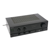
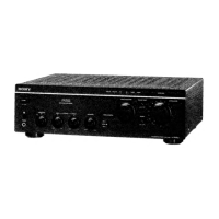
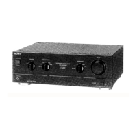
Identifies and labels the various controls and jacks on the front panel.

Connection Notes

Offers essential notes and precautions for making proper audio connections.

Section 1 General

Section 2 Block Diagram

Section 3 Electrical Adjustments

Bias Current Adjustment

Procedure for adjusting bias current for optimal performance.

Section 4 Diagrams

Circuit Boards Location

Locates various circuit boards within the unit for service.

Semiconductor Lead Layouts

Illustrates lead configurations for semiconductor components.

IC Block Diagrams

Provides block diagrams illustrating the functionality of integrated circuits.

Printed Wiring Boards

Displays printed wiring board layouts for component placement and routing.

Section 6 Exploded Views

Front Panel Assembly

Lists parts and their assembly order for the front panel.

Chassis Assembly

Lists parts and their assembly order for the main chassis.

Section 7 Electrical Parts List

Accessory & Packing Material

Related product manuals