EasyManua.ls Logo

Sony TA-FE370 Service Manual

Sony TA-FE370
24 pages
To Next Page IconTo Next Page
Page #1 background imageLoading...
Page #1 background image
SERVICE MANUAL
INTEGRATED STEREO AMPLIFIER
AEP Model
UK Model
SPECIFICATIONS
TA-FE370/FE570
Photo: TA-FE570 (BLACK)
Ver 1.0 2001.04
9-873-838-11 Sony Corporation
2001D0500-1 Home Audio Company
C 2001.4 Shinagawa Tec Service Manual Production Group
Amplifier section
DIN power output
TA-FE570: 110 W + 110 W
(4 ohms at 1 kHz)
TA-FE370: 70 W + 70 W
(4 ohms at 1 kHz)
Frequency response
PHONO (20 Hz - 20 kHz): RIAA equalization curve
±1.0 dB
TUNER, CD, AUX, TAPE1/DAT, TAPE2/MD:
7 Hz - 70 kHz
+
0
3
dB
S/N (network A)
PHONO: 80 dB
TUNER, CD, AUX, TAPE1/DAT, TAPE2/MD:
105 dB
Output voltage/impedance
RECOUT: 200 mV, 1 kilohm
PHONES: 5 mW (at 8 ohms)
Speakers impedance 4 - 16 ohms
Damping factor 80 (8 ohms, 1 kHz)
General
System
Power amplifier with all stages directly coupled
Preamplifier: Low-noise, equalizer
amplifier
Power requirements 230 V AC, 50/60 Hz
Power consumption
TA-FE570: 190 W
TA-FE370: 160 W
0.6 W
(In standby mode)
Dimensions (approx.) (w/h/d)
430 x 135 x 310 mm
incl. projecting parts and
controls
Mass (approx.)
TA-FE570: 6.5 kg
TA-FE370: 5.5 kg
Supplied accessories
Remote commander (remote) RM-S325 (1)
Sony batteries R6 (size-AA) (2)
Design and specifications are subject to change
without notice.

Other manuals for Sony TA-FE370

Question and Answer IconNeed help?

Do you have a question about the Sony TA-FE370 and is the answer not in the manual?

Sony TA-FE370 Specifications

General IconGeneral
Dimensions (WxDxH)430 x 310 x 135 mm
Power requirements230V; 50/60Hz
I/O portsAudio Input - 6.0 Audio Output - 2.0 Headphone Output Speaker Selector A
Connectivity technologyWired
Frequency range7 - 70000 Hz
Power consumption (standby)0.5 W
Power consumption (typical)160 W
Weight and Dimensions IconWeight and Dimensions
Weight550 g

Summary

Specifications

Amplifier Specifications

Detailed specifications for the amplifier section including power output, frequency response, and S/N.

General Unit Specifications

Overall system specifications, power requirements, dimensions, mass, and supplied accessories for the unit.

Servicing Notes

Model Identification and Board Handling

Information on identifying different models and specific settings for main board handling.

Critical Safety Component Warnings

Crucial safety warnings for critical components and proper replacement procedures.

General Information

Control Layout and Functions

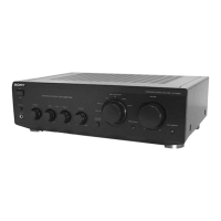
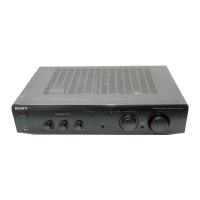
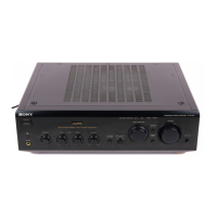
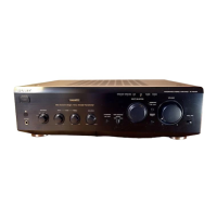
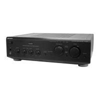
Detailed overview of front and back panel controls, buttons, jacks, and indicators.

Disassembly Procedures

Case and Main Board Removal

Step-by-step guide for disassembling the unit, including case and main board removal.

Front Panel Assembly Removal

Procedure for carefully removing the front panel assembly.

Diagrams and Schematics

Circuit Board Layouts and Diagrams

Notes on diagram conventions, circuit board locations, and various schematic/wiring diagrams.

Exploded Views

Case Section Exploded View

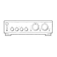
Visual guide of the case assembly with part identification and screws.

Front Panel Section Exploded View

Exploded diagram of the front panel components and their part numbers.

Chassis Section Exploded View

Exploded view of the chassis, showing main boards, transformers, and power cord.

Electrical Parts List

Semiconductors, Diodes, and LEDs

List of transistors, diodes, and LEDs with part numbers and descriptions.

Capacitors, Resistors, and Switches

Details on capacitors, resistors, variable resistors, and switches with specifications.

ICs, Connectors, Jacks, and Coils

List of integrated circuits, connectors, jacks, and coils used in the unit.

Accessories and Packing Materials

Information on supplied accessories, manuals, and packing materials.

Revision History

Revision Log

Record of document versions, dates, and descriptions of revisions.

Related product manuals