2
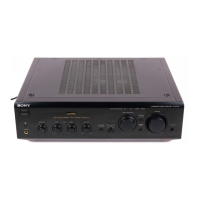
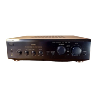
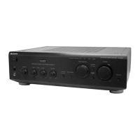
TA-FE370/FE570
SAFETY-RELATED COMPONENT WARNING!!
COMPONENTS IDENTIFIED BY MARK 0 OR DOTTED
LINE WITH MARK 0 ON THE SCHEMATIC DIAGRAMS
AND IN THE PARTS LIST ARE CRITICAL TO SAFE
OPERATION. REPLACE THESE COMPONENTS WITH
SONY PARTS WHOSE PART NUMBERS APPEAR AS
SHOWN IN THIS MANUAL OR IN SUPPLEMENTS PUB-
LISHED BY SONY.
TABLE OF CONTENTS
1. SERVICING NOTES ............................................... 2
2. GENERAL
Location of Controls ....................................................... 3
3. DISASSEMBLY
3-1. Disassembly Flow ........................................................... 4
3-2. Case ................................................................................. 4
3-3. Front Panel Assy ............................................................. 5
3-4. MAIN Board ................................................................... 5
4. DIAGRAMS
4-1. Note for Printed Wiring Boards
and Schematic Diagrams ................................................ 7
4-2. Printed Wiring Board – MAIN Board – ........................ 8
4-3. Schematic Diagram – MAIN Board – ............................ 9
4-4. Printed Wiring Boards – CONTROL/SPEAKER SW/
VOLUME/Boards – ........................................................ 10
4-5. Schematic Diagram – CONTROL/SPEAKER SW/
VOLUME Boards – ........................................................ 11
4-6. Printed Wiring Boards
– AC OUTLET/HEADPHONE/LOUDNESS/
POWER SW/STANDBY Boards –................................. 12
4-7. Schematic Diagram
– AC OUTLET/HEADPHONE/LOUDNESS/
POWER SW/STANDBY Boards –................................. 13
4-8. IC Pin Function Description ........................................... 14
5. EXPLODED VIEWS
5-1. Case Section .................................................................... 15
5-2. Front Panel Section ......................................................... 16
5-3. Chassis Section ............................................................... 17
6. ELECTRICAL PARTS LIST ............................... 18
SECTION 1
SERVICING NOTES
IN
RECOUT
IN
PHONO
IN
TUNER
IN IN
RECOUT
IN
CD AUX TAPE2/MD TAPE1/DAT
EON CONTROL
AC OUTLET
SPEAKERS
L
R
IMPEDANCE USE 4 - 16 Ω
SWITCHED 100W MAX
+
–
+
–
RL
S
I
G
N
A
L
G
N
D
U
IN
PART No.
Model PART No.
TA-FE570: AEP model 4-233-359-0
[]
TA-FE570: UK model 4-233-359-1
[]
TA-FE370: AEP model 4-233-359-2
[]
TA-FE370: UK model 4-233-359-3
[]
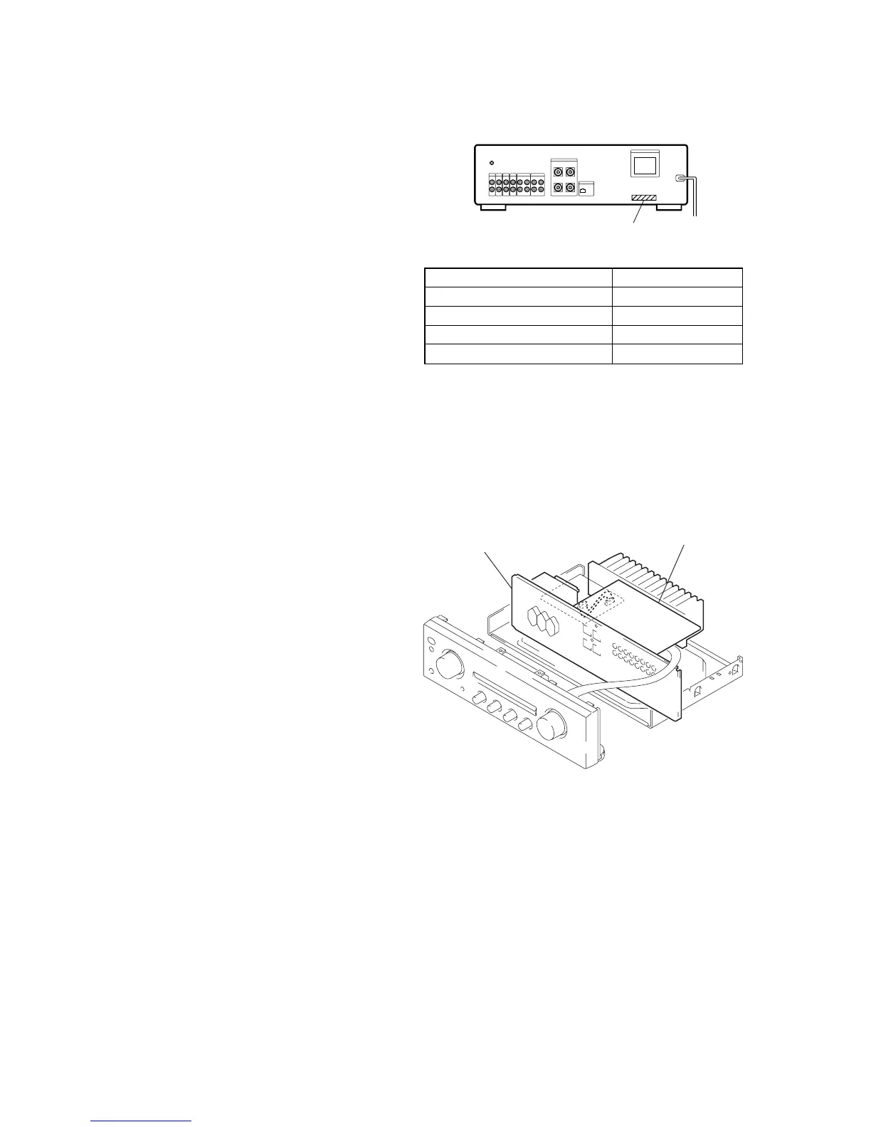
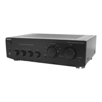
MAIN BOARD SETTING
On AEP model of this set, AC outlet is mounted onto the AC OUT-
LET board holding the back panel between. Since removing the
MAIN board alone is difficult, in repairing the MAIN board, handle
the MAIN board with the back panel connected as shown in the
figure below.
back panel
MAIN board
MODEL IDENTIFICATION
– Back Panel –