15
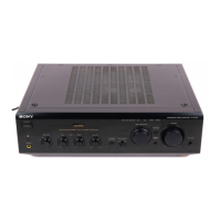
TA-FE370/FE570
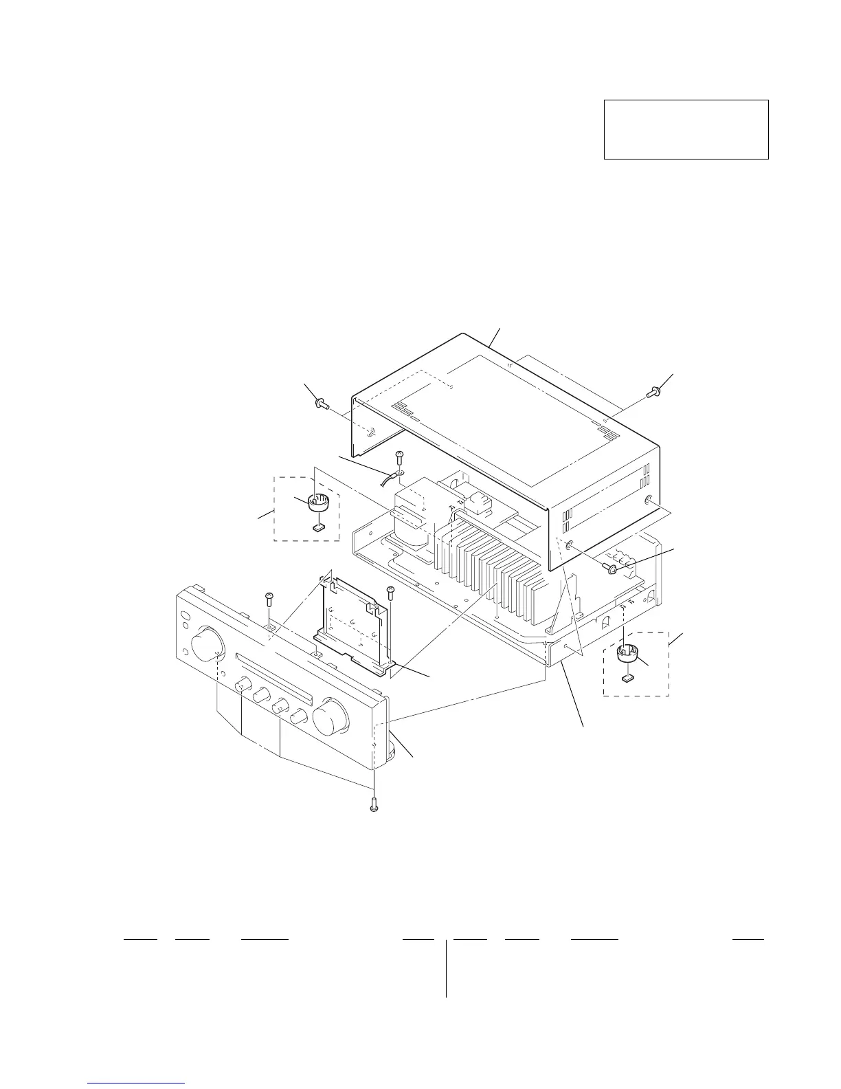
5-1. CASE SECTION
SECTION 5
EXPLODED VIEWS
The components identified by
mark 0 or dotted line with mark
0 are critical for safety.
Replace only with part number
specified.
• Items marked “*” are not stocked since they
are seldom required for routine service. Some
delay should be anticipated when ordering
these items.
• The mechanical parts with no reference num-
ber in the exploded views are not supplied.
• Accessories and packing materials is given in
the last of the electrical parts list.
NOTE:
• -XX and -X mean standardized parts, so they
may have some difference from the original
one.
• Color Indication of Appearance Parts
Example:
KNOB, BALANCE (WHITE) . . . (RED)
↑↑
Parts Color Cabinet's Color
Ref. No. Part No. Description Remark
Ref. No. Part No. Description Remark
1 X-4953-448-1 FOOT ASSY
2 4-232-237-01 FOOT (DIA. 30)
3 4-210-291-01 SCREW (CASE 3 TP2) (BLACK)
3 4-210-291-11 SCREW (CASE 3 TP2) (SILVER)
4 4-233-360-11 CASE (BLACK)
4 4-233-360-31 CASE (SILVER)
#1 7-685-646-79 SCREW +BVTP 3X8 TYPE2 N-S)
2
1
#1
not supplied
Front panel section
Chassis section
not supplied
#1
#1
#1
2
3
3
3
4
1