Do you have a question about the Sony TA-F333ESL and is the answer not in the manual?
Technical specifications detailing power output, bandwidth, distortion, and noise levels.
Information regarding specification labels and model identification details.
Description of the preamplifier and power amplifier sections.
Details on the power supply voltage and frequency requirements for different regions.
Table showing power consumption figures for various models and regions.
Specifications for the AC outlet feature, including wattage limits.
Instructions for setting the operating voltage based on local power supply.
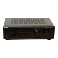
Detailed explanation of the function of each control on the front panel of the unit.
Explains the operation of the remote commander for amplifier, tuner, CD, and tape deck controls.
Information regarding battery life, replacement, and avoiding leakage.
Procedure for disassembling the front panel components of the unit.
Steps involved in the disassembly of the main chassis case.
Instructions for removing and disassembling the back panel assembly.
Procedure for accessing and disassembling the Main (A) circuit board.
Procedure for accessing and disassembling the Main (B) circuit board.
Method for checking and verifying the functionality of the Main (B) board.
Instructions for the proper disassembly of the switch mechanism.
Steps and procedures for the correct assembly of the switch mechanism.
Procedure for performing the offset adjustment on the unit's circuitry.
Procedure for adjusting the bias current for optimal performance.
Overall system block diagram illustrating the functional connections.
Diagram showing the physical location of all circuit boards within the unit.
Layouts of the printed wiring boards for component placement reference.
Detailed schematic diagrams of the unit's electronic circuitry for troubleshooting.
Exploded view diagram of the external cabinet and its assembly parts.
Exploded view diagram of the front chassis and related components.
Exploded view diagram of the main chassis and internal assembly parts.
List of electrical components for the Main (A) board, including part numbers.
List of electrical components for the Main (B) board, including part numbers.
List of electrical components for the EQ board, including part numbers.
List of electrical components for the FUNCTION board, including part numbers.
Components list for SP-SW, SP TERMINAL, and TONE boards.
List of electrical components for the INPUT board, including part numbers.
Components list for PREOUT and CONTROL boards.
Components list for SW (F), EYE, OUTLET, and V.S boards.
Details about the remote commander accessory included with the unit.
List of instruction manuals included with the product.
Information on individual cartons for specific model packaging.
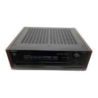
| Type | Integrated Amplifier |
|---|---|
| Frequency Response | 2Hz to 100kHz |
| Input Sensitivity | 0.17mV (MC), 2.5mV (MM), 150mV (line) |
| Signal-to-Noise Ratio | 76dB (MC), 93dB (MM), 105dB (line) |
| Damping factor | 100 |
| Dimensions | 430 x 150 x 375mm |
| Weight | 12.3kg |
| Total harmonic distortion | 0.004% |
| Speaker load impedance | 4 ohms to 16 ohms |