EasyManua.ls Logo

Sony TA-FE300R Service Manual

Sony TA-FE300R
16 pages
To Next Page IconTo Next Page
Page #1 background imageLoading...
Page #1 background image
MICROFILM
TA-FE300R/FE500R
INTEGRATED STEREO AMPLIFIER
AEP Model
E Model
TA-FE300R/FE500R
UK Model
Australian Model
TA-FE300R
SERVICE MANUAL
SPECIFICATIONS
Photo: TA-FE500R
Amplifier section
DIN power output
TA-FE500R: 75 W+75 W (4 ohms at 1 kHz)
55 W+55 W (8 ohms at 1 kHz)
TA-FE300R: 50 W+50 W (4 ohms at 1 kHz)
40 W+40 W (8 ohms at 1 kHz)
Frequency response
PHONO (20 Hz-20 kHz): RIAA equalization curve
±0.5 dB
TUNER, CD, AUX, TAPE1/DAT,
TAPE2/MD: 7 Hz-70 kHz dB
S/N (network A)
PHONO: 80dB
TUNER, CD, AUX, TAPE1/DAT,
TAPE2/MD: 105 dB
Output voltage/ impedance
REC OUT: 200 mV, 1 kilohm
PHONES: 5 mW (at 8 ohms)
Speakers impedance:
4-16 ohms, 8-16 ohms (SPEAKERS A+B)
Damping factor
TA-FE500R: 60 (8 ohms, 1 kHz)
General
System
Power amplifier: Pure-complementary SEPP OCL
power amplifier with all stages directly coupled
Preamplifier. Low-noise, equalizer amplifier
Power requirements
Models not supplied with a voltage selector:
220-230 V AC, 50/60 Hz
Models supplied with a voltage selector:
120, 220, or 240 V AC, 50/60 Hz
Power consumption
TA-FE500R: 160 W
TA-FE300R: 120 W
Dimensions (approx.) (w/h/d):
430×105×290 mm
incl. projecting parts and controls
Mass (approx.)
TA-FE500R: 4.7 kg
TA-FE300R: 4.3 kg
Supplied accessories
Remote commander (remote) (1)
RM-S315
Sony batteries SUM-3 (NS) (2)
Design and specifications are subject to change without
notice.
+0
–3
Question and Answer IconNeed help?

Do you have a question about the Sony TA-FE300R and is the answer not in the manual?

Sony TA-FE300R Specifications

General IconGeneral
Frequency Response10 Hz - 50 kHz
Input sensitivity2mV (MM), 150mV (line)
Signal-to-Noise Ratio100 dB
Dimensions430 x 132 x 330 mm (W x H x D)
Signal to noise ratio100 dB
Speaker load impedance4 - 16 ohms
Total Harmonic Distortion0.03%

Summary

SPECIFICATIONS

Amplifier section

Technical specifications for the amplifier circuitry.

General

General technical specifications including power, dimensions, and mass.

SECTION 1 GENERAL

1-1. Index to Parts and Controls

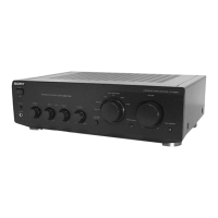
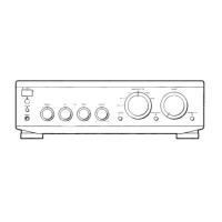
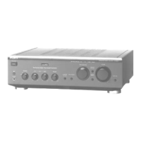
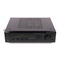
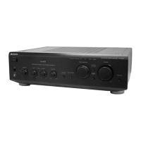
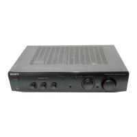
Details about front and rear panel controls and their functions.

SECTION 2 DIAGRAMS

2-1. CIRCUIT BOARDS LOCATION

Illustrates the physical placement of various circuit boards within the unit.

2-2. IC PIN FUNCTION DESCRIPTION

Details pin functions for specific ICs used in the control board.

2-4. PRINTED WIRING BOARDS

Shows the layout of printed wiring boards for major sections of the device.

SECTION 3 EXPLODED VIEWS

(1) CASE, FRONT PANEL SECTION

Exploded view of the front panel components and chassis.

(2) CHASSIS SECTION

Exploded view of the internal chassis and related components.

SECTION 4 ELECTRICAL PARTS LIST

< CONNECTOR >

List of connectors for external and internal connections.

< SWITCH >

List of switches for device controls and functions.

< CAPACITOR >

List of capacitors with specifications like capacitance, voltage, and type.

< DIODE >

List of diodes with part numbers and types.

Related product manuals