EasyManua.ls Logo

Sony TA-FE510R Service Manual

Sony TA-FE510R
17 pages
To Next Page IconTo Next Page
Page #1 background imageLoading...
Page #1 background image
TA-FE310R/FE510R
AEP Model
TA-FE310R/FE510R
UK Model
TA-FE310R
SERVICE MANUAL
INTEGRATED STEREO AMPLIFIER
MICROFILM
SPECIFICATIONS
Photo : TA-FE510R
Amplifier section
DIN power output
TA-FE510R: 80 W+80 W (4 ohms at 1 kHz)
60 W+60 W (8 ohms at 1 kHz)
TA-FE310R: 55 W+55 W (4 ohms at 1 kHz)
45 W+45 W (8 ohms at 1 kHz)
Frequency response
PHONO (20 Hz-20 kHz): RIAA equalization curve
±0.5 dB
TUNER, CD, AUX, TAPE1/DAT,
TAPE2/MD: 7 Hz-70 kHz dB
S/N (network A)
PHONO: 80dB
TUNER, CD, AUX, TAPE1/DAT,
TAPE2/MD: 105 dB
Output voltage/ impedance
REC OUT: 200 mV, 1 kilohm
PHONES: 5 mW (at 8 ohms)
Speakers impedance:
4-16 ohms, 8-16 ohms (SPEAKERS A+B)
Damping factor
80 (8 ohms, 1 kHz)
General
System
Power amplifier: Pure-complementary SEPP OCL
power amplifier with all stages directly coupled
Preamplifier. Low-noise, equalizer amplifier
Power requirements
Models not supplied with a voltage selector:
220-230 V AC, 50/60 Hz
Power consumption
TA-FE510R: 160 W
TA-FE310R: 120 W
Dimensions (approx.) (w/h/d):
430×105×300 mm
incl. projecting parts and controls
Mass (approx.)
TA-FE510R: 4.8 kg
TA-FE310R: 4.3 kg
Supplied accessories
Remote commander (remote) (1)
RM-S315
Sony batteries SUM-3 (NS) (2)
Design and specifications are subject to change without
notice.
Question and Answer IconNeed help?

Do you have a question about the Sony TA-FE510R and is the answer not in the manual?

Sony TA-FE510R Specifications

General IconGeneral
TypeIntegrated Amplifier
Signal-to-Noise Ratio100 dB
Dimensions430 x 135 x 310mm
Weight8.5 kg
Speaker load impedance4-16 ohms
Frequency Response10 Hz - 100 kHz
Input sensitivity150 mV (line)

Summary

SECTION 1 GENERAL

Index to Parts and Controls

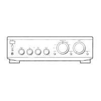
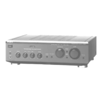
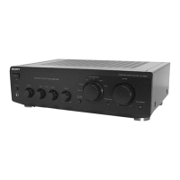
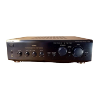
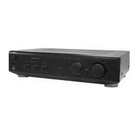
Overview of parts and controls on the front and rear panels of the unit.

SECTION 2 DIAGRAMS

Circuit Boards Location

Visual representation of the location of various circuit boards within the unit.

IC Pin Function Description

Details the function of each pin for specified integrated circuits.

Schematic Diagram - Main Section

Detailed circuit schematic for the main section of the amplifier.

Printed Wiring Board - Main Section

Shows the physical layout of components and traces on the main printed circuit board.

Schematic Diagram - Panel Section

Circuit schematic focusing on the front panel controls and indicators.

Printed Wiring Board - Panel Section

Physical layout of components and traces for the panel sections.

Schematic Diagram - Power Section

Circuit diagram illustrating the power supply and related components.

SECTION 3 EXPLODED VIEWS

Case, Front Panel Section

Exploded view showing the assembly of the front panel and casing.

Chassis Section

Exploded view illustrating the internal chassis and component arrangement.

SECTION 4 ELECTRICAL PARTS LIST

AC SW CONTROL

Lists electrical components for the AC switch and control sections.

Accessories & Packing Materials

Lists accessories and packing materials included with the unit.

Hardware List

Lists screws and other hardware used in the assembly.

Related product manuals