Do you have a question about the Sony TA-FE610R and is the answer not in the manual?
| Type | Integrated Amplifier |
|---|---|
| Power Output | 100 W per channel (8 ohms) |
| Frequency Response | 10 Hz - 100 kHz |
| Signal-to-Noise Ratio | 100 dB |
| Inputs | 4 x Line, 1 x Phono |
| Dimensions | 430 x 150 x 350 mm |
| Weight | 12.5 kg |
| Impedance | 8Ω |
| Total harmonic distortion | 0.03% |
| Input sensitivity | 2.5 mV (Phono), 150 mV (Line) |
Detailed technical parameters of the amplifier section including power output and frequency response.
Overall specifications of the unit including power requirements, consumption, dimensions, and mass.
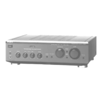
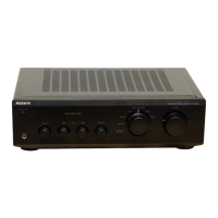
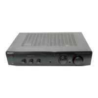
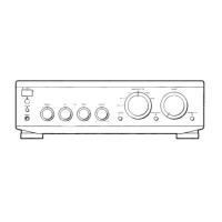
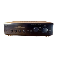
Identifies and describes front panel buttons, knobs, indicators, and jacks for operation.
Lists and describes rear panel input/output terminals and connectors for connectivity.
Details the step-by-step procedure for adjusting bias using semi-fixed resistors and a voltmeter.
Illustrates the physical placement of various internal circuit boards within the unit.
Lists pin assignments and functions for IC902, the Input Control LED Driver.
Presents the schematic for the panel section, including notes on components and signal paths.
Shows component placement and routing on the panel section printed wiring board.
Details the circuit diagram for the main A board, including voltage points and signal paths.
Illustrates component positions and routing on the main A board's printed wiring board.
Presents the schematic for the main B board, including IC block diagrams and circuit details.
Shows the layout and routing of components on the main B board's printed wiring board.
Detailed illustration of front panel components and their assembly order.
Diagram showing the internal chassis components and their arrangement and mounting.
Lists electrical components for the EON, HP, and INPUT circuit boards.
Lists electrical components for the LED and Main A circuit boards.
Lists electrical components for the Main A and Main B circuit boards.
Lists electrical components for the Main B, Outlet, and Panel circuit boards.
Lists electrical components specifically for the Panel circuit board.
Lists electrical components for Panel, Pro Ind, SP SW, SP TM, and Trans circuit boards.
Lists components for the Vol board, plus accessories and packing materials.