EasyManua.ls Logo

Sony TA-KMSW500 Service Manual

Sony TA-KMSW500
24 pages
To Next Page IconTo Next Page
Page #1 background imageLoading...
Page #1 background image
SERVICE MANUAL
Sony Corporation
Audio & Video Business Group
Published by Sony EMCS (Malaysia) PG Tec
SPECIFICATIONS
POWER AMPLIFIER
9-890-522-04
2009K80-1
©
2009.11
E Model
Australian Model
Canadian Model
TA-KMSW500
Ver. 1.3 2009.11
TA-KMSW500 is the ampli er section in HT-DDW5500/DDW7500/DDW8500.
Design and speci cations are subject to change
without notice.
Power amplifier (TA-KMSW500)
RMS output (6 ohms, 80 Hz, THD 10%)
200 W per channel
1)
2)
185 W per channel
Input LINE IN (input pin jacks)
1)
Measured under the following conditions:
2)
Measured under the following conditions:
Area code Power requirements
E51, SP, SAF, MY 240 V AC, 50 Hz
EA 127 V AC, 60 Hz
CND 120 V AC, 60 Hz
AR, AUS, TH 230 V AC, 50 Hz
Area code Power requirements
AR, TH 220 V AC, 50 Hz
• Abbreviation
AR : Argentina model
AUS : Australian model
EA : Saudi Arabia model
E51 : Chilean and Peruvian models
MY : Malaysia model
SAF : South African model
SP : Singapore model
CND : Canadian model
TH : Thai model
Question and Answer IconNeed help?

Do you have a question about the Sony TA-KMSW500 and is the answer not in the manual?

Sony TA-KMSW500 Specifications

General IconGeneral
BrandSony
ModelTA-KMSW500
CategoryAmplifier
LanguageEnglish

Summary

SPECIFICATIONS

Power Amplifier Specifications

Details RMS output and input specifications for the TA-KMSW500.

Power Requirements by Area Code

Lists power requirements (voltage, frequency) for different geographical area codes.

Model Abbreviation Reference

Provides a list of abbreviations used for different country or region models.

SAFETY AND HANDLING NOTES

Chip Component Replacement Notes

Important notes regarding the safe replacement of chip components, especially tantalum capacitors.

Unleaded Solder Information

Explains the characteristics, usage, and marking of unleaded solder.

GENERAL INFORMATION

Front Panel Controls Overview

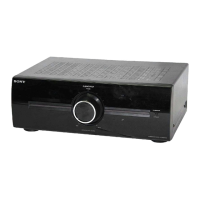
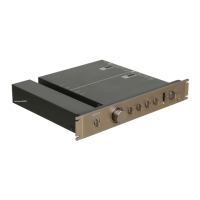
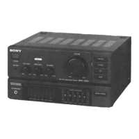
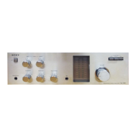
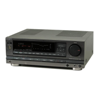
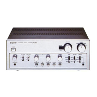
Identifies and describes controls and indicators on the unit's front panel.

Rear Panel Connections Overview

Identifies and describes connectors and ports on the unit's rear panel.

DISASSEMBLY PROCEDURES

Case Disassembly Procedure

Step-by-step instructions for disassembling the outer case of the unit.

Back Panel Section Disassembly

Procedure for disassembling the back panel section, including component identification.

Front Panel Section Disassembly

Procedure for disassembling the front panel section, including component identification.

Main Board Section Disassembly

Instructions on how to disassemble and access the main board section.

CIRCUIT DIAGRAMS

System Block Diagram

High-level block diagram showing functional units and signal flow.

Main Board Printed Wiring Diagram

Physical layout of components on the main board's printed wiring.

Main Board Schematic Diagram

Detailed schematic diagram for the main circuit board.

LED/Volume Control Printed Wiring Diagrams

Printed wiring board layouts for LED and Volume Control sections.

LED/Volume Control Schematic Diagrams

Schematic diagrams for the LED and Volume Control circuit boards.

Integrated Circuit (IC) Block Diagrams

Block diagrams and pin functions for specific ICs used in the unit.

EXPLODED VIEWS

Case Exploded View

Exploded view of the unit's case, showing screws and external parts.

Front Panel Exploded View

Exploded view detailing front panel components and their part numbers.

Back Panel Exploded View

Exploded view of back panel components, including fan and connectors.

Chassis Exploded View

Exploded view of the chassis, showing internal boards, transformers, and fuses.

ELECTRICAL PARTS LIST

Left LED Board Parts List

Parts list for the Left LED Board, including capacitors, diodes, and resistors.

Main Board Parts List

Parts list for the Main Board, covering various components.

Right LED Board Parts List

Parts list for the Right LED Board, detailing resistors and diodes.

Volume Control Board Parts List

Parts list for the Volume Control Board, including resistors and potentiometers.

REVISION HISTORY

Related product manuals