SERVICE MANUAL
AV AMPLIFIER
AEP Model
UK Model
SPECIFICATIONS
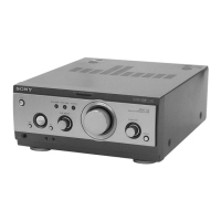
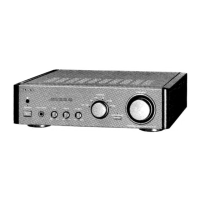
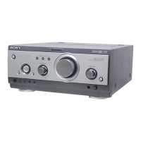
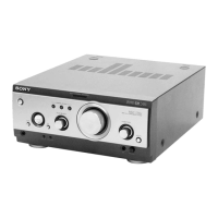
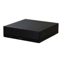
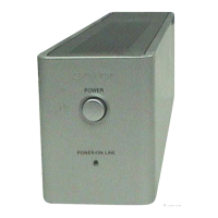
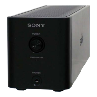
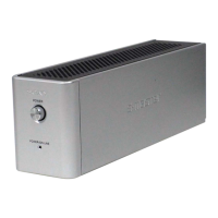
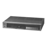
TA-S3
Ver 1.0 2001.05
9-873-874-11 Sony Corporation
2001E0500-1 Home Audio Company
C 2001.5 Shinagawa Tec Service Manual Production Group
TA-S3 is the Amplifier section in
MHC-S3.
Amplifier section
DIN power output (rated) 60 + 60 watts
(6 ohms at 1 kHz, DIN)
Continuous RMS power output (reference)
80 + 80 watts
(6 ohms at 1 kHz, 10%
THD)
Music power output (reference)
150 + 150 watts
(6 ohms at 1 kHz, 10%
THD)
Inputs
VIDEO (AUDIO) IN: voltage 250 mV,
(phono jacks) impedance 47 kilohms
MD IN: voltage 450 mV,
(phono jacks) impedance 47 kilohms
OPTICAL IN:
(Square optical connector jacks, rear panel)
wavelength 700 nm
Outputs
MD OUT: voltage 250 mV
(phono jacks) impedance 1 kilohms
PHONES: accepts headphones of
(stereo mini jack) 8 ohms or more
FRONT SPEAKER: accepts impedance of 6 to
16 ohms
SUB WOOFER OUT: Voltage 1 V,
impedance 1 kilohms
General
Power requirements 230 V AC, 50/60 Hz
Power consumption 180 watts
0.6 watts (during Power
Saving Mode)
Dimensions (w/h/d)
Approx. 280 x 128 x 350 mm
Mass Approx. 6.2 kg
Design and specifications are subject to change
without notice.
w
w
w
.
x
i
a
o
y
u
1
6
3
.
c
o
m
Q
Q
3
7
6
3
1
5
1
5
0
9
9
2
8
9
4
2
9
8
T
E
L
1
3
9
4
2
2
9
6
5
1
3
9
9
2
8
9
4
2
9
8
0
5
1
5
1
3
6
7
3
Q
Q
TEL 13942296513 QQ 376315150 892498299
TEL 13942296513 QQ 376315150 892498299
http://www.xiaoyu163.com
http://www.xiaoyu163.com