SERVICE MANUAL
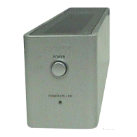
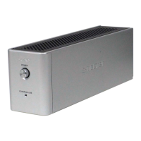
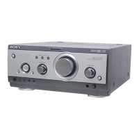
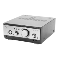
SURROUND AMPLIFIER
US Model
Canadian Model
AEP Model
UK Model
E Model
Australian Model
SPECIFICATIONS
TA-SB500WR
Ver 1.1 2007.02
9-879-016-02
2007B05-1
© 2007.02
Sony Corporation
Home Audio Division
Published by Sony Techno Create Corporation
• TA-SB500WR is the amplifier section in DAV-LF10/
DAV-SB500W/WAHT-SD1.
• Refer to the supplement-1 of this service manual for
TA-SB500WR in WAHT-SD1.
AUDIO POWER SPECIFICATIONS
for the US model
POWER OUTPUT AND
TOTAL HARMONIC
DISTORTION: With 4 ohm loads, both
channels driven, from
200 – 20,000 Hz; rated
65 watts per channel
minimum RMS power,
with no more than 0.7 %
total harmonic distortion
from 250 milli watts to
rated output.
Amplifier section
Stereo mode (rated) 86 W + 86 W (4 ohms at
1 kHz, THD 10 %)
Surround mode (reference) music power output
for DAV-LF10:
86 W*
(with SS-TSL11)
for DAV-SB500W: 96 W + 96 W*
(with SS-TS11)
*Depending on the sound field settings and the source,
there may be no sound output.
Surround amplifier
Power requirements
North American models: 120 V AC, 60 Hz
Taiwan model: 120 V AC, 50/60 Hz
Other models: 220-240 V AC, 50/60 Hz
Power consumption 36 W (120 V AC)
36 W (220-240 V AC)
Dimensions (approx.) 65 × 90 × 335 mm
(2
5
/
8
× 3
5
/
8
× 13
1
/
4
inches) (w/h/d) incl.
speaker cord cover
Mass (approx.) 1.3 kg (2 lb 14 oz)
Design and specifications are subject to change
without notice.
w
w
w
.
x
i
a
o
y
u
1
6
3
.
c
o
m
Q
Q
3
7
6
3
1
5
1
5
0
9
9
2
8
9
4
2
9
8
T
E
L
1
3
9
4
2
2
9
6
5
1
3
9
9
2
8
9
4
2
9
8
0
5
1
5
1
3
6
7
3
Q
Q
TEL 13942296513 QQ 376315150 892498299
TEL 13942296513 QQ 376315150 892498299
http://www.xiaoyu163.com
http://www.xiaoyu163.com