EasyManua.ls Logo

Sony TA-VA777ES User Manual

Sony TA-VA777ES
78 pages
To Next Page IconTo Next Page
Page #1 background imageLoading...
Page #1 background image
TA-VA777ES
AEP Model
UK Model
SERVICE MANUAL
INTEGRATED AV AMPLIFIER
MICROFILM
— Continued on next page —
SPECIFICATIONS
Manufactured under license from Dolby Laboratories
Licensing Corporation.
Dolby, “DOLBY”, the double-D symbol ;, AC-3 and
“Pro Logic” are trademarks of Dolby Laboratories
Licensing Corporation.
Audio section
POWER OUTPUT
Stereo mode 120 W + 120 W
(8 ohms, DIN 1 kHz)
100 W + 100 W
(4 ohms, DIN 1 kHz)
100 W + 100 W
(8 ohms, THD 0.05%
20 – 20 kHz)
90 W + 90 W
(4 ohms, THD 0.05%
20 – 20 kHz)
Surround mode
Front: 120 W + 120 W
Center
a)
: 120 W
Rear
a)
: 120 W + 120 W
(8 ohms, DIN 1 kHz)
Front: 100 W + 100 W
Center
a)
: 100 W
Rear
a)
: 100 W + 100 W
(4 ohms, DIN 1 kHz)
a) Depending on the sound field settings and
the source, there may be no sound output.
Frequency response
PHONO:
20 Hz ~ 20 kHz
RIAA ±0.5 dB
LINE (TUNER, CD,
MD/DAT, TAPE,
DVD, TV/LD,
VIDEO 1, 2, and
VIDEO 3):
10 Hz ~ 100 kHz
+0.5/–2.0 dB
(ANALOG DIRECT)
Signal-to-noise ratio
DIGITAL IN: 100 dB
(20 kHz LPF, A)
PHONO: 86 dB*
(A, 5mV)
LINE: 100 dB*
(20 kHz LPF, A)
* ANALOG DIRECT
Inputs (Analog)
PHONO:
Sensitivity: 4 mV
Impedance:
50 kilohms
LINE (TUNER, CD,
MD/DAT, TAPE,
DVD, TV/LD,
VIDEO 1, 2, and
VIDEO 3):
Sensitivity: 200 mV
Impedance:
50 kilohms
Inputs (Digital)
Coaxial (DVD, CD):
Sensitivity: –
Impedance: 75 ohms
Optical (DVD, TV/LD,
MD/DAT):
Sensitivity: –
Impedance: –

Table of Contents

Question and Answer IconNeed help?

Do you have a question about the Sony TA-VA777ES and is the answer not in the manual?

Sony TA-VA777ES Specifications

General IconGeneral
Speaker load impedance4 - 16 ohms
Frequency Response5Hz-100kHz (+0, -3dB)
Input Impedance47k Ohms (Line)
Dimensions430 x 160 x 430 mm (W x H x D)
TypeIntegrated Amplifier
Power Output100 W per channel (8 ohms)

Summary

General Information

Front Panel Overview

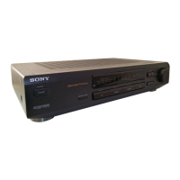
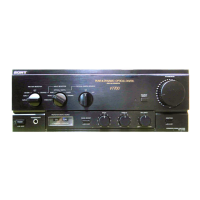
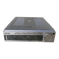
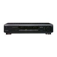
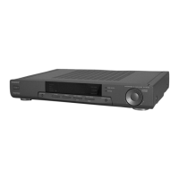
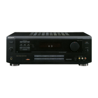
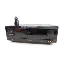
Describes the components and layout of the front panel controls and indicators.

Rear Panel Connectivity

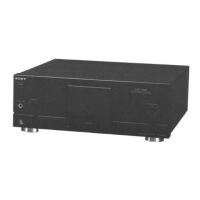
Details the various input/output jacks and terminals on the rear panel.

Adjustments

Electrical Adjustments

Provides instructions for performing electrical adjustments, specifically BIAS adjustment.

Diagrams and Schematics

Block Diagram - Main Section

Shows the overall signal flow and major functional blocks of the system.

Block Diagram - Digital Section

Details the signal paths and components within the digital processing section.

Block Diagram - Control Section

Outlines the control signals and system management logic.

Block Diagram - Power Section

Illustrates the power distribution and regulation circuits.

Schematic Diagram - Audio Section

Provides the detailed circuit diagram for the audio processing stages.

Schematic Diagram - Video Section

Shows the circuit diagram for the video signal processing and switching.

Schematic Diagram - AMP Section (1/2)

Detailed circuit diagram for the amplifier stages.

Schematic Diagram - AMP Section (2/2)

Continuation of the amplifier circuit diagram.

Schematic Diagram - Power Supply Section

Circuit diagram detailing power supply voltages and regulation.

IC Pin Function Descriptions

Details the function of each pin for specific integrated circuits.

Related product manuals