EasyManua.ls Logo

Sony TA-V606 User Manual

Sony TA-V606
31 pages
To Next Page IconTo Next Page
Page #1 background imageLoading...
Page #1 background image
Inputs
S/N (weighting
Sensitivity Impedance network, input
level)
75 dB*
PHONO 2.5mV 50 kilohms
(A, 2.5mV)
82 dB*
TUNER 150mV 50 kilohms
(A, 150mV)
82 dB*
CD 200mV 50 kilohms
(A, 200mV)
TAPE/MD,VIDEO1, 2, 3 150mV
50 kilohms
82 dB*
TV/LD (AEP, UK model) 150mV
(A, 150mV)
TV/LD
82 dB*
(EXCEPT AEP, UK model)
250mV 50 kilohms
(A, 250mV)
82 dB*
5.1 INPUT 200mV 50 kilohms
(A, 200mV)
* ’78 IHF
Outputs VIDEO 1, 2, 3, AUDIO OUT :
Voltage : 150 mV, Impedance : 10 kilohms
WOOFER :
Voltage : 2 V
Impedance : 1 kilohms
PHONES :
Accepts low and high impedance headphones
BASS BOOST +10 dB at 70 Hz
TONE ± 8 dB at 100Hz and 10 kHz
MICROFILM
Manufactured under license from Dolby Laboratories Licensing
Corporation.
“Dolby”, the double-D symbol a and “Pro Logic” are trademarks
of Dolby Laboratories Licensing Corporation.
INTEGRATED AV AMPLIFIER
Photo : TA-VE610
AEP Model
UK Model
E Model
TA-VE610
Chinese Model
TA-V606
SERVICE
MANUAL
TA-V606/ VE610
SPECIFICATIONS
Amplifier section
POWER OUTPUT
Stereo mode V606 : (6 ohms 1kHz, THD 0.7 %)
110 W + 110W
VE610 : (4 ohms 1kHz, THD 0.7 %)
100 W + 100W
Surround mode V606 : (6 ohms at 1kHz, THD 0.7 %)
Front : 110 W/ch
Center* : 110 W
Rear* : 110 W/ch
VE610 : (4 ohms at 1kHz, THD 0.7 %)
Front : 100 W/ch
Center* : 100 W
Rear* : 100 W/ch
*Depending on the sound field settings and the
source, sound will not be output.
5.1 mode V606 : (6 ohms at 1kHz, THD 0.7 %)
Front : 110 W/ch
Center : 110 W
Rear : 110 W/ch
VE610 : (4 ohms at 1kHz, THD 0.7 %)
Front : 100 W/ch
Center : 100 W
Rear : 100 W/ch
Harmonic distortion at rated output
Less than 0.09% (with DIRECT PASS on)
Frequency respones
PHONO : RIAA equalization curve
± 0.5dB
CD, TAPE, DAT/MD, VIDEO 1, 2 :
+0
10Hz – 50 kHz – 1 dB (with DIRECT PASS on)
– Continued on page 2 –
Question and Answer IconNeed help?

Do you have a question about the Sony TA-V606 and is the answer not in the manual?

Sony TA-V606 Specifications

General IconGeneral
Frequency Response7Hz to 100kHz
Input Sensitivity2.5mV (MM), 150mV (line)
Speaker load impedance4Ω to 16Ω
Dimensions430 x 150 x 360mm
Signal-to-Noise Ratio100dB (MM)

Summary

Specifications Overview

Amplifier Specifications

Details amplifier output, harmonic distortion, and frequency response.

Input Specifications

Lists sensitivity and impedance for various audio/video inputs.

Output Specifications

Details voltage and impedance for audio outputs.

Safety Component Warning

Highlights critical components for safe operation, requiring specific part numbers.

SECTION 1 GENERAL

Front Panel Control Layout

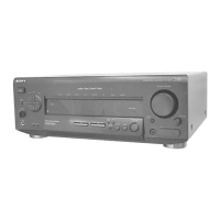
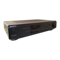
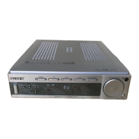
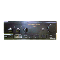
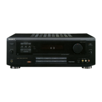
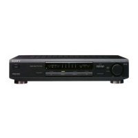
Identifies and describes controls and indicators on the front panel.

Rear Panel Connections

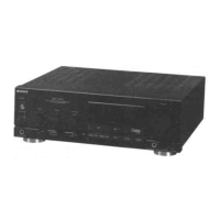
Details the various input and output connectors on the rear panel.

Remote Control Functions

Lists and describes the functions of the remote control buttons.

SECTION 2 DIAGRAMS

IC Pin Functionality

Details pin functions for specific ICs, aiding in circuit analysis.

Circuit Board Locations

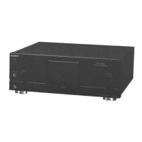
Illustrates the physical placement of various circuit boards within the unit.

Printed Wiring Boards - Surround Section

Shows the layout and component placement for surround section wiring.

Schematic Diagram - Surround Section

Provides the detailed circuit schematic for the surround section.

Schematic Diagram - Amplifier Section

Provides the detailed circuit schematic for the amplifier section.

Printed Wiring Boards - Amplifier Section

Shows the layout and component placement for amplifier section wiring.

Printed Wiring Boards - Display Section

Shows the layout and component placement for display section wiring.

Schematic Diagram - Display Section

Provides the detailed circuit schematic for the display section.

IC Block Diagrams

Provides block diagrams for ICs in surround, amplifier, and display sections.

SECTION 6 EXPLODED VIEWS

Front Panel Exploded View

Shows the assembly and part numbers for the front panel section.

Back Panel Exploded View

Shows the assembly and part numbers for the back panel section.

Chassis Exploded View

Shows the assembly and part numbers for the chassis section.

SECTION 4 ELECTRICAL PARTS LIST

Capacitor and Connector Parts

Lists part numbers and specifications for capacitors and connectors.

Jack and Resistor Parts

Lists part numbers and specifications for jacks and resistors.

Amplifier Section Components

Lists diodes, ICs, coils, transistors, and resistors for the AMP section.

AMP, AU-VIDEO, AUDIO, AUDIO SW Components

Lists capacitors, connectors, jacks, relays, and terminals for these sections.

Audio SW, CONT (AS-1), CONT (AS-2) Components

Lists connectors, ICs, transistors, resistors, and capacitors for these boards.

Display and L.B.SW Components

Lists diodes, ICs, transistors, and resistors for display and L.B.SW sections.

Display, L.B.SW, HP, Rear Amp Components

Lists diodes, transistors, and resistors for these sections.

Rear Amp, S-A-SP, S.Video, Secondary Components

Lists ICs, jacks, coils, transistors, and resistors for these boards.

Secondary SP Components

Lists diodes, coils, transistors, resistors, relays, and vibrator for the SP section.

SP, SP SW, Standby, SURR Components

Lists terminals, fuses, ICs, transistors, resistors, transformers, and capacitors.

SURR Components (Capacitors)

Lists capacitors for the SURR board.

SURR Components (Transistor, Resistor)

Lists transistors and resistors for the SURR board.

SURR Components (Relay, Vibrator)

Lists relays and vibrator for the SURR board.

SURR, SURR-AUDIO, SW, VIDEO Components

Lists connectors, resistors, and switches for these boards.

VIDEO, VIDEO (3), VOL Components

Lists capacitors, jacks, variable resistors, connectors, miscellaneous, accessories, and hardware.