EasyManua.ls Logo

Sony TA-VE150 User Manual

Sony TA-VE150
29 pages
To Next Page IconTo Next Page
Page #1 background imageLoading...
Page #1 background image
MICROFILM
SERVICE MANUAL
INTEGRATED AV AMPLIFIER
AEP Model
UK Model
Amplifier section
Power output
Stereo mode (DIN 1 kHz, 8 ohms)
25 W + 25 W
Surround mode (DIN 1 kHz, 8 ohms)
Front: 25 W/ch
Centre: 25 W
Rear: 25 W/ch
5.1 CH (DIN 1 kHz, 8 ohms)
INPUT/DVD mode Front: 25 W/ch
Centre: 25 W
Rear: 25 W/ch
Frequency response TV, VIDEO, DVD-2CH,
5.1 CH INPUT/DVD:
20 Hz-50 kHz ± 1 dB
Inputs
Sensitivity Impedance S/N
(weighting network, input level)
TV, VIDEO, DVD-2CH, 200 mV 50 82 dB*
5.1 CH INPUT/DVD kilohms (A, 150 mV)
*’78 IHF
Outputs VIDEO (AUDIO OUT):
Voltage 200 mV,
Inpedance 10 kilohms
WOOFER/AUDIO OUT:
Voltage: 2 V
Impedance: 1 kilohms
Muting Full mute
BASS BOOST +9 dB at 70 Hz
General
Power requirements 230 V AC, 50/60 Hz
Power consumption 115 W
Dimensions 430 × 274 × 64.5 mm
Mass (Approx.) 5.4 kg
Supplied accessories Remote controller
(remote) (1)
Size AA (R6) batteries (2)
Scart adaptor (1)
Design and specifications are subject to change without notice.
Specifications indicated are measured at 230 VAC, 50 HZ.
SPECIFICATIONS
TA-VE150
This amplifier has the Dolby Surround system.
Manufactured under license from Dolby Laborato-
ries Licensing Corporation.
“Dolby”, the double-D symbol a and “Pro Logic” are
trademarks of Dolby Laboratories Licensing Corpo-
ration.
Question and Answer IconNeed help?

Do you have a question about the Sony TA-VE150 and is the answer not in the manual?

Sony TA-VE150 Specifications

General IconGeneral
TypeStereo Amplifier
Channels2
Power Output50W
Total Output Power100W
Output Power (Stereo)50W
Frequency Response10Hz - 100kHz
Input Impedance47 kOhms
Dimensions430 x 360 x 120 mm
Surround Sound FormatsDolby Pro Logic
InputsRCA
OutputsSpeaker outputs

Summary

Specifications

Amplifier Specifications

Covers power output, stereo/surround modes, and frequency response.

Output and General Specifications

Details output types, dimensions, power requirements, and mass.

Disassembly Procedures

Case and Front Panel Disassembly

Steps for removing the case and front panel assembly.

Main Board Removal

Instructions for detaching the main board.

Test Modes

Initial Mode Operations

Details for activating and understanding the Initial Mode.

Factory and Other Test Modes

Describes Factory, FL Check, Gain Up, and Version modes.
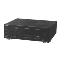
Electrical Parts List

Related product manuals