Do you have a question about the Sony TC-177SD and is the answer not in the manual?
Visual representation of the TC-177SD's functional blocks.
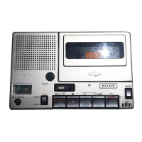
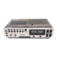
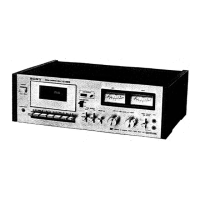
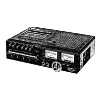
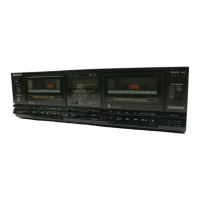
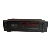
Photographs showing the exterior of the TC-177SD unit.
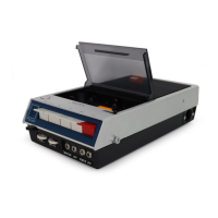
Photographs showing the interior layout of the TC-177SD unit.
Step-by-step guide for removing the cassette lid.
Instructions for disassembling the main unit case.
First set of mechanical adjustments including tape path and head height.
Second set of mechanical adjustments including torque and switch positions.
Calibrating the monitor signal output level.
Adjusting the record circuit for DOLBY NR performance.
Adjusting the playback circuit for DOLBY NR performance.
Adjusting the calibration tone level and frequency.
Aligning playback head for optimal stereo separation.
Setting the playback output signal level accurately.
Adjusting playback frequency response for tape types.
Measuring the signal-to-noise ratio during playback.
Calibrating the VU meters to indicate 0 VU correctly.
Verifying the limiter circuit's functionality.
Ensuring balance between microphone input controls.
Ensuring balance between line input/output controls.
Aligning record head for optimal signal recording.
Setting record input signal level for different tapes.
Adjusting bias current for optimal recording.
Adjusting playback filters for minimum noise.
Measuring bias leakage to ensure low noise.
Measuring unit's frequency response across various tapes.
Measuring overall signal-to-noise ratio.
Measuring the performance of the 19 kHz filter.
Measuring S/N improvement with DOLBY NR.
Measuring the effectiveness of the erase head.
Measuring signal bleed between stereo channels.
Measuring signal bleed between tape tracks.
Measuring the accuracy of tape playback speed.
Diagrams illustrating signal levels within the unit.
Detailed circuit schematic of the TC-177SD (part 1).
Diagram showing component mounting locations (part 1).
Diagram showing component mounting locations (part 2).
Detailed circuit schematic of the TC-177SD (part 2).
Illustration of disassembled unit components (part 1).
Illustration of disassembled unit components (part 2).
Illustration of disassembled unit components (part 3).
Illustration of disassembled unit components (part 4).
Illustration of disassembled unit components (part 5).
Details regarding the packaging of the unit.
List of screws used in the TC-177SD.
Definitions and examples of hardware terms.
| Brand | Sony |
|---|---|
| Model | TC-177SD |
| Category | Cassette Player |
| Language | English |