EasyManua.ls Logo

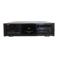
Sony TC-K333ESG - Repair and Maintenance Guidelines; Flexible Circuit Board Repair; Chip Component Replacement; Operating Voltage Configuration

Sony TC-K333ESG
35 pages
To Next Page IconTo Next Page
To Previous Page IconTo Previous Page
Loading...
TC-K333ESG/K950ES
TABLE
OF
CONTENTS
section
Title
Page
SPECIFICATIONS
i
a
ee
ee
1
MODEL
IDENTIFICATION
re
ee
ee
3
SAFETY
CHECK-OUT
cress
ecssecccccercccescceceees
3
1.
GENERAL
+++ee
errr
rere
cette
eee
e
eter
eeeeeeeeeennees
4
2.
DISASSEMBLY
rrr
re
ee
ee
5
3.
ADJUSTMENTS
3-1.
Mechanical
Adjustments
-++sssssrrreee
reer
7
3-2.
Electrical
Adjustments
:+++++s+rerteeeer
eres
10
4.
DIAGRAMS
4-1-1.
IC
Block
Diagrams+-++++seereseeeeeeeeees
15
4-2-1.
IC503,
505
(CX20188)
Pin
Functions::::-
15
4-2-2.
IC801
(M50964-220SP)
Pin
Functions
---
16
4-1-2.
Ic
Block
Diagrams
Corer
reer
verre
sceseees
17
4-3,
Block
Diagram
cecsrsrrtseee
eect
e
er
eeeeeeees
17
4-4,
Semiconductor
Lead
Layouts
-+++++++-+++*>
21
4-5.
Circuit
Boards
Location
-sr++ssssrrereeeees
21
4-6.
Printed
Wiring
Boards
Audio
Section
cceerer
reece
eee
eeeeeeees
22
4-7,
Schematic
Diagram
|
Audio
Section
cerrrserercecetereeeeeees
27
4-8.
Printed
Wiring
Boards
—Syscon
Section
srrrrerscrereceseeeeeees
32
4-9.
Schematic
Diagram
Syscon
section
rr
ee
37
5.
EXPLODED
VIEWS
5-1.
Panel
Section
-crrssercreee
eset
sere
enc
cree
42
5-2.
Chassis Section
«cssccesece
reece
eeeeeeceeees
44
5-8.
Mechanism
Section
(1)
(TCM~200D1)
srrerecercee
eer
eeceeeeeeeenees
A5
5-4.
Mechanism
Section
(2)
(TCM-200D1)
srrrereereceecereeeeecseneeens
46
6.
ELECTRICAL
PARTS
LIST
--++csscrreeeeeeeeeeeee
AT
SAFETY-RELATED
COMPONENT
WARNING!!
COMPONENTS
IDENTIFIED
BY
MARK
A
OR
DOTTED
LINE
WITH
MARK
A
ON
THE
SCHEMATIC
DIAGRAMS
AND
IN
THE
PARTS
LIST
ARE
CRITICAL
TO
SAFE
OPERATION.
REPLACE
THESE
COMPONENTS
WITH
SONY
PARTS
WHOSE
PART
NUMBERS
APPEAR
AS
SHOWN
IN
THIS
MANUAL
OR
IN
SUPPLEMENTS
PUB-
LISHED
BY
SONY.
Flexible
Circuit
Board
Repairing
*
Keep
the
temperature
of
the
soldering
iron
around
270
during
repairing,
*
Do
not
touch
the
soldering
iron
on
the
same
conductor
of
the
circuit
board
(within
3
times).
*
Be
careful
not
to
apply
force
on
the
conductor
when
soldering
or
unsoldering.
Notes
on
chip
component
replacement
«
Never
reuse
a
disconnected
chip
component.
«
Notice
that
the
minus
side
of
a
tantalum
capacitor
may
be
damaged
by
heat,
Dolby
noise
reduction
and
HX
Pro
headroom
extension
manufactured
under
license
from
Dolby
Laboratories
Licensing
Corporation.
HX
Pro
originated
by
Bang
&
Olufsen.
Operating
voltage
.
Before
connecting
the
unit
to
the
power
source,
check
that
the
operational
voltage
of
your
unit
is
the
same
as
the
local
power
supply.
Where
purchased
|
Operating
voltage
AEP,
WG
model
|
220
V
AC,
50/60
Hz
UK
model
240
V
AC,
50
Hz
US,
120
V
AC,
60
Hz
Canadian
model
E
model
120,
220
or
240
V
AC
adjustable,
50/60
Hz
A
voltage
selector
is
located
on
the
rear
panel.
If
the
selector
must
be
reset,
disconnect
the
AC
power
cord
and
set
the
selector
to
the
appropriate
voltage.
VOLTAGE
selector
VOLTAGE
ATTENTION
AU
COMPOSANT
AYANT
RAPPORT
A
LA
SECURITE!
LES
COMPOSANTS
IDENTIFIES
PAR
UNE
MARQUE
/\
SUR
LES
DIAGRAMMES
SCHEMATIQUES
ET
LA
LISTE
DES
PIECES
SONT
CRITIQUES
POUR
LA
SECURITE
DE
FONCTIONNEMENT.
NE
REMPLACER
CES
COM-
POSANTS
QUE
PAR
DES
PIECES
SONY
DONT
LES
NUMEROS
SONT
DONNES
DANS
CE
MANUEL
OU
DANS
LES
SUPPLEMENTS
PUBLIES
PAR
SONY.
—_2—

Related product manuals