EasyManua.ls Logo

Sony TC-K670 Service Manual

Sony TC-K670
34 pages
To Next Page IconTo Next Page
Page #1 background imageLoading...
Page #1 background image
Photo:
TC-K677ES
SPECIFICATIONS
Recording
system
4-track
2-channel
stereo
Fast-winding
time
Approx.
90
sec.
(with
Sony
C-60
cassette)
Bias
AC
bias
Heads
Erasing
head
x
1
(S&F
head)
Recording
head
x
1
(Permalloy
head)
Playback
head
x
1
(LA
head)
Motors
Capstan
motor
x
1
(DC
servo
motor)
Reel
motor
x
1
(DC
motor)
ASIST(mechanical
drive)
motor
x
1
(DC
motor)
Signal-to-noise
ratio
(at
peak
level)
oe
ON ON
Type
lV(Sony
METAL-SLT/S)
Type
II(Sony
UX-S)
Total
harmonic
distortion
1.0%
(with
Sony
METAL-SLT/S
cassette)
Frequency
response
(DOLBY
NR
OFF)
20—21,000
Hz
(+3
dB,
IEC)
20-—16,000
Hz
[+3
dB
OVU
(-4dB)
recording]
20-19,000
Hz
(+3
dB,
IEC)
Type
IV
cassette
(Sony
METAL-SLT/S)
Type
II
cassette
(Sony
UX-S)
Type
|
cassette
|
(Sony
HF-S)
Wow
and
flutter
20—17,000
Hz
(£3
dB,IEC)
pia
+0.09%
W.Peak
(IEC)
0.05%
WRMS
(NAB)
+0.14%
W.Peak
(DIN)
Dolby
Laboratories
Licensing
Corporation.
ma}
Dolby
Laboratories
Licensing
Corporation.
“DOLBY”
and
the
double-D
symbol!
0]
are
trademarks
of
Canadian
Model
AEP
Model
UK
Model
E
Model
TC-K570
US
Model
AEP
Model
TC-K670
US
Model
Canadian
Model
UK
Model
TC-K677ES
Model
Name
Using
Similar
Mechanism
Line
inputs
Sensitivity
77.5
mV
(phono
jacks)
input
impedance
|
47
k
ohms
CD
DIRECT
INPUT!
Input
impedance
|
47k
ohms
Outputs
Tape
Transport
Mechanism
Type
Inputs
0.32
V
at
a
load
impedance
of
47
k
ohms
Over
10
k
ohms
0-1.25
mW
ata
load
impedance
of
32
ohms
Line
outputs
(phono
jacks)
Rated
output
levei
Load
impedance
Headphones
(stereo
phone
jack)
Output
level
General
Power
requirements
US,Canadian
model:
TC-K570:
120V
AC
60Hz
18W
TC-K670,
K677ES:120V
AC
60Hz
19W
AEP,
Germany
model:
220VAC~
50/60Hz
UK
model:
240VAC~50/60Hz
E
model:
120,
220,
240VAC~50/60Hz
18W
Power
consumption
19
W
Dimensions
Approx.
430
x
123
x
300
mm
(w/h/d)
(17
x
4’
x
117
inches)
including
projecting
parts
and
controls
Weight
Approx.
4.9
kg
(10
ibs
13
oz)
Supplied
accessories
Audio
connecting
cords
(2)
Design
and
specifications
subject
to
change
without
notice.
Note
This
appliance
conforms
with
EEC
Directive
87/308/EEC
regarding
interference
suppression.
STEREO
CASSETTE
DECK
ONY.
Dolby
noise
reduction
manufactured
under
license
from
Question and Answer IconNeed help?

Do you have a question about the Sony TC-K670 and is the answer not in the manual?

Sony TC-K670 Specifications

General IconGeneral
Track System4-track, 2-channel stereo
Tape Speed4.8 cm/s
Tape TypesNormal, Chrome, Metal
Output0.5V (line)
InputsLine In
TypeCassette Deck
Heads3 (Record, Playback, Erase)
Noise ReductionDolby B, C
Frequency Response20 Hz - 20 kHz
Wow and Flutter0.04% (WRMS)
OutputsLine Out, Headphone

Summary

Specifications

Recording and Playback Specifications

Details on recording system, fast-winding, bias, heads, motors, and signal-to-noise ratio.

Performance Specifications

Covers total harmonic distortion, frequency response, and wow/flutter for different tape types.

Safety and Leakage Testing

Safety Check-out Procedure

Instructions for performing safety checks on exposed metal parts for AC leakage.

Leakage Test Methods

Outlines three methods for measuring AC leakage current according to safety standards.

Component Safety Warning

Identifies critical safety components and specifies replacement guidelines.

Front Panel Controls and Indicators

Front Panel Control Identification

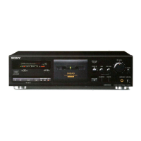
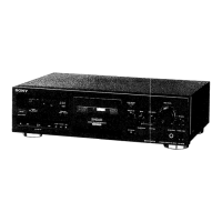
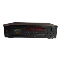
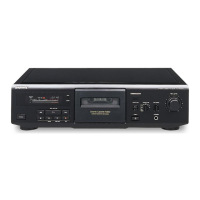
Lists and describes all front panel buttons, switches, indicators, and controls.

Disassembly Procedures

Mechanical Adjustments

Tape Path Adjustment

Procedure to adjust tape path for optimal performance and prevent tape curling.

Mechanical Adjustment Procedures

Pinch Roller and Head Height Adjustment

Steps for adjusting pinch roller and record/playback head height for proper tape tracking.

Head Declination and Azimuth Adjustment

Procedures for setting head declination and preliminary azimuth alignment for optimal playback.

Mechanical Adjustment Details

Erasehead Adjustment Procedures

Steps for adjusting erasehead azimuth, height, and depth for effective tape erasure.

Electrical Adjustments

Playback Output Level Matching

Steps to adjust and match output levels for L-CH and R-CH, ensuring consistency within 1 dB.

Electrical Adjustment Procedures

Tape Speed and Bias Current Adjustment

Procedures for adjusting tape speed using a frequency counter and bias consumption current.

Playback Level and Record Bias Adjustment

Methods for adjusting playback levels using test tapes and setting record bias parameters.

Electrical Adjustment Details

Record Level Adjustment

Procedure for setting and confirming record signal levels to meet specified adjustment limits.

Erase Current Adjustment

Steps to adjust erase current and verify the erasehead frequency for optimal performance.

Diagrams and Schematics

Schematic Diagrams

Detailed circuit schematics for the Audio Section and System Control Section.

Electrical Parts List - Boards and General Components

Electrical Parts List - Diodes, ICs, and Filters

Electrical Parts List - Resistors (R101-R262)

Electrical Parts List - Resistors (R263-R581)

Electrical Parts List - Resistors (R582-R735)

Electrical Parts List - Resistors (R736-R826)

Related product manuals