EasyManua.ls Logo

Sony TC-K570 - Service Manual

Sony TC-K570
34 pages
To Next Page IconTo Next Page
Loading...
Photo:
TC-K677ES
SPECIFICATIONS
Recording
system
4-track
2-channel
stereo
Fast-winding
time
Approx.
90
sec.
(with
Sony
C-60
cassette)
Bias
AC
bias
Heads
Erasing
head
x
1
(S&F
head)
Recording
head
x
1
(Permalloy
head)
Playback
head
x
1
(LA
head)
Motors
Capstan
motor
x
1
(DC
servo
motor)
Reel
motor
x
1
(DC
motor)
ASIST(mechanical
drive)
motor
x
1
(DC
motor)
Signal-to-noise
ratio
(at
peak
level)
oe
ON ON
Type
lV(Sony
METAL-SLT/S)
Type
II(Sony
UX-S)
Total
harmonic
distortion
1.0%
(with
Sony
METAL-SLT/S
cassette)
Frequency
response
(DOLBY
NR
OFF)
20—21,000
Hz
(+3
dB,
IEC)
20-—16,000
Hz
[+3
dB
OVU
(-4dB)
recording]
20-19,000
Hz
(+3
dB,
IEC)
Type
IV
cassette
(Sony
METAL-SLT/S)
Type
II
cassette
(Sony
UX-S)
Type
|
cassette
|
(Sony
HF-S)
Wow
and
flutter
20—17,000
Hz
(£3
dB,IEC)
pia
+0.09%
W.Peak
(IEC)
0.05%
WRMS
(NAB)
+0.14%
W.Peak
(DIN)
Dolby
Laboratories
Licensing
Corporation.
ma}
Dolby
Laboratories
Licensing
Corporation.
“DOLBY”
and
the
double-D
symbol!
0]
are
trademarks
of
Canadian
Model
AEP
Model
UK
Model
E
Model
TC-K570
US
Model
AEP
Model
TC-K670
US
Model
Canadian
Model
UK
Model
TC-K677ES
Model
Name
Using
Similar
Mechanism
Line
inputs
Sensitivity
77.5
mV
(phono
jacks)
input
impedance
|
47
k
ohms
CD
DIRECT
INPUT!
Input
impedance
|
47k
ohms
Outputs
Tape
Transport
Mechanism
Type
Inputs
0.32
V
at
a
load
impedance
of
47
k
ohms
Over
10
k
ohms
0-1.25
mW
ata
load
impedance
of
32
ohms
Line
outputs
(phono
jacks)
Rated
output
levei
Load
impedance
Headphones
(stereo
phone
jack)
Output
level
General
Power
requirements
US,Canadian
model:
TC-K570:
120V
AC
60Hz
18W
TC-K670,
K677ES:120V
AC
60Hz
19W
AEP,
Germany
model:
220VAC~
50/60Hz
UK
model:
240VAC~50/60Hz
E
model:
120,
220,
240VAC~50/60Hz
18W
Power
consumption
19
W
Dimensions
Approx.
430
x
123
x
300
mm
(w/h/d)
(17
x
4’
x
117
inches)
including
projecting
parts
and
controls
Weight
Approx.
4.9
kg
(10
ibs
13
oz)
Supplied
accessories
Audio
connecting
cords
(2)
Design
and
specifications
subject
to
change
without
notice.
Note
This
appliance
conforms
with
EEC
Directive
87/308/EEC
regarding
interference
suppression.
STEREO
CASSETTE
DECK
ONY.
Dolby
noise
reduction
manufactured
under
license
from
Question and Answer IconNeed help?

Do you have a question about the Sony TC-K570 and is the answer not in the manual?

Sony TC-K570 Specifications

General IconGeneral
Track System4-track, 2-channel stereo
TypeCassette Deck
Heads1 x playback, 1 x erase
MotorDC Servo Motor
Tape TypeMetal
Frequency Response20Hz - 20kHz (Metal tape)
Signal to Noise Ratio75dB (dolby C)
InputLine
OutputLine
Dimensions430 x 125 x 315mm
OutputsLine Output
InputsLine Input
Tape Speed4.76 cm/s

Summary

Device Specifications

Performance Specifications

Details performance metrics including recording, playback, frequency response, wow/flutter, S/N, and THD.

Mechanical and Input;Output Specs

Covers tape transport mechanism, input/output levels, general specifications, power, dimensions, and weight.

Safety Procedures and Warnings

Safety Check-out and Leakage Testing

Outlines the procedure for safety checks and AC leakage testing on the device.

Critical Component Safety Alert

Highlights components critical for safe operation and the need for specific replacement parts.

Front Panel Identification

Front Panel Controls and Indicators

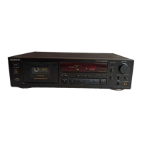
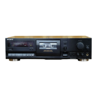
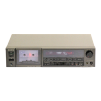
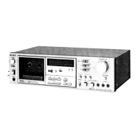
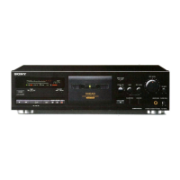
Identifies and describes the function of each button, control, and indicator on the front panel.

Remote Control Operation

Details the capability to control the cassette deck using remote commanders.

Disassembly Guidelines

Mechanism Block and Cassette Holder Removal

Step-by-step instructions for disassembling the main mechanism block and cassette holder.

Mechanical Component Disassembly

Ornamental Plate and Pinch Lever Assemblies

Details the disassembly of the ornamental plate and pinch lever assemblies for different models.

Capstan Motor, Flywheel, and Reel;Assist Motors

Provides disassembly steps for capstan motor, flywheel, and reel/assist motors.

Microcomputer Pin Assignments

IC701 M50941-483 SP Pinout Details

Lists pin assignments, names, I/O types, and detailed descriptions for the M50941-483SP microcomputer.

Mechanical Adjustments Overview

Adjustment Precautions and Preparation

Covers general precautions, required tools, and setup for mechanical adjustments.

Tape Path and Terminology Guide

Guides on adjusting the tape path, including definitions of adjustment terms.

Mechanical Adjustment Procedures

Pinch Roller and Head Adjustments

Details adjustments for the supply pinch roller and record/playback head height and declination.

Erasehead and Azimuth Adjustment

Covers adjustments for erasehead declination, height, depth, and preliminary azimuth settings.

Tape Path Check and Waveform Analysis

Describes how to check the tape path and analyze the resurge waveform.

Erasehead and Torque Adjustments

Erasehead Alignment and Depth

Details the adjustment of the erasehead azimuth, height, and depth for optimal performance.

Torque and Pinch Roller Force Measurement

Explains how to measure and adjust torque values and pinch roller pressing force.

Electrical Adjustments - Playback

Playback Head Level and Azimuth

Details adjustments for playback head level, azimuth, and phase checks using test tapes.

Playback Head Azimuth Procedure

Step-by-step procedure for adjusting the record/playback head azimuth.

Electrical Adjustments - Speed and Bias

Tape Speed Adjustment

Details the procedure for adjusting the tape speed using a frequency counter.

Bias Consumption Current Adjustment

Details the procedure for adjusting bias consumption current.

Playback Level Adjustment

Explains how to adjust playback level settings for L-CH and R-CH.

Record Bias Adjustment

Details the procedure for adjusting record bias settings.

Electrical Adjustments - Record and Erase

Record Level Adjustment

Procedure for adjusting the record level for optimal recording performance.

Erase Current Adjustment

Procedure for adjusting the erase current to ensure proper tape erasure.

Diagrams and Schematics

Printed Wiring Boards and Circuit Board Locations

Provides diagrams of printed wiring boards and identifies the locations of various circuit boards.

Semiconductor Lead Layouts

Illustrates the lead layouts for semiconductor components used in the device.

Audio and System Control Schematics

Presents schematic diagrams for the audio section and the system control section.

Exploded Views - Chassis Section

Chassis Section Components

Details the components of the chassis section through an exploded view diagram.

Exploded Views - Front Panel Section

Front Panel Section Components

Details the components of the front panel section through an exploded view diagram.

Exploded Views - Mechanism Section 1

Mechanism Section 1 Parts List

Lists and illustrates components for the first part of the mechanism section.

Exploded Views - Mechanism Section 2

Mechanism Section 2 Parts List

Lists and illustrates components for the second part of the mechanism section.

Electrical Parts List - Main Board

FL(A) Board Components

Lists electrical components found on the FL(A) board, including capacitors, connectors, diodes, ICs, and resistors.

MAIN(A) Board Components (Part 1)

Lists electrical components for the MAIN(A) board, including transistors, resistors, switches, and transformers.

Electrical Parts List - Main Board (Continued)

MAIN(A) Board Capacitors and Connectors

Continues the list of electrical components for the MAIN(A) board, focusing on capacitors and connectors.

Electrical Parts List - Main Board (Continued)

MAIN(A) Board Capacitors and Switches

Continues the list of electrical components for the MAIN(A) board, detailing capacitors, switches, and connectors.

Electrical Parts List - Main Board (Continued)

MAIN(A) Board Diodes, ICs, Jacks, Coils, Filters

Lists diodes, ICs, jacks, coils, and filters for the MAIN(A) board.

Electrical Parts List - Main Board (Continued)

MAIN(A) Board Transistors and Resistors (Part 1)

Lists transistors and resistors for the MAIN(A) board.

Electrical Parts List - Main Board (Continued)

MAIN(A) Board Resistors (Part 2)

Continues the list of resistors for the MAIN(A) board.

Electrical Parts List - Main Board (Continued)

MAIN(A) Board Resistors (Part 3)

Continues the list of resistors for the MAIN(A) board.

Electrical Parts List - Real Motor

Real Motor Components (Resistors, Switches, Transformers, Capacitors)

Lists resistors, switches, transformers, and capacitors for the real motor section.

Miscellaneous and Hardware

Miscellaneous Parts and Hardware List

Lists miscellaneous parts, hardware, and their descriptions.

Accessory and Packing Materials

Lists accessory items and packing materials, including instruction manuals.

Service Manual Supplement Information

Supplement-1 Details

Information regarding Supplement-1, noting the addition of the Australian Model.

Service Manual Correction Notices

Correction-1 Details

Details corrections for specific panel part numbers on page 29 of the service manual.

Service Manual Correction Notices

Correction-2 Details

Details corrections for a specific spring part number on page 29 of the service manual.

Related product manuals