Do you have a question about the Sony TC-KE300 and is the answer not in the manual?
Procedure for testing AC leakage current from exposed metal parts.
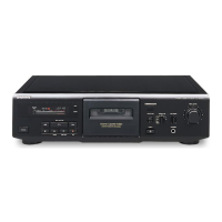
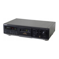
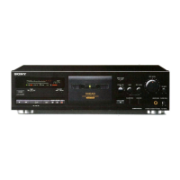
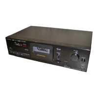
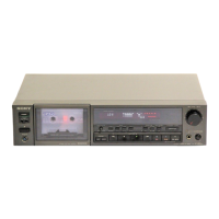
Lists and identifies all controls and indicators on the front panel of the cassette deck.
Step-by-step instructions for removing the front panel assembly.
Procedure for detaching the main mechanism deck from the chassis.
Instructions for removing the erase and record/playback heads and pinch rollers.
Details on how to remove the fitting base block assembly.
Steps for removing the capstan and reel motors.
Procedures for adjusting mechanical aspects like torque and tension.
Procedures for calibrating electrical performance and settings.
How to adjust playback signal levels for optimal performance.
Procedure for adjusting bias consumption current, typically after head replacement.
Steps to adjust and verify the tape speed accuracy.
Method for setting the recording bias level for optimal sound quality.
Procedure to set the recording input level for accurate signal capture.
Layout diagrams for the main printed circuit boards.
Circuit diagrams for the main section of the unit.
Circuit diagrams specific to the TC-KE400S model.
Layout diagrams for the main printed circuit boards of the TC-KE400S.
Identifies the physical location of various circuit boards within the unit.
Layout diagrams for the audio section printed circuit boards.
Circuit diagrams for the audio section of the unit.
Visual representation of key signal waveforms at different test points.
Exploded view showing the main chassis and associated parts.
Exploded view illustrating the components of the front panel assembly.
Exploded view of the first part of the tape transport mechanism.
Exploded view of the second part of the tape transport mechanism.
| Brand | Sony |
|---|---|
| Model | TC-KE300 |
| Category | Cassette Player |
| Language | English |