Do you have a question about the Sony TC-KE400S and is the answer not in the manual?
Methods and limits for testing AC leakage current from exposed metal parts.
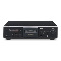
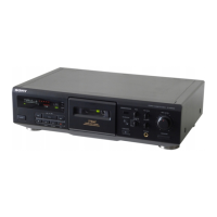
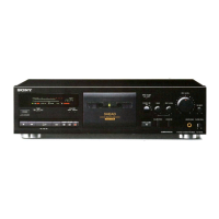
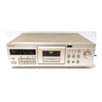
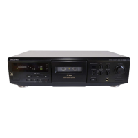
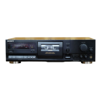
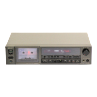
Identifies and explains the function of each component on the front panel.
Step-by-step guide to removing the front panel assembly.
Instructions for removing the main tape mechanism deck.
Procedures for detaching heads, pinch rollers, and motors.
Instructions for adjusting mechanical aspects like torque and tension.
Procedures to adjust playback signal levels and tape transport speed.
Procedure for adjusting bias current when replacing head assembly or transformer.
Details of pins and functions for the CXP82612-022Q system control IC.
Printed wiring board layouts and schematic diagrams for the main section.
Visual guide indicating the physical location of all circuit boards.
Printed wiring board layouts and schematic diagrams for the audio section.
Exploded diagram showing the main chassis components and assembly.
Exploded diagram of the front panel components.
Exploded diagrams of the tape mechanism components.
List of capacitors with their specifications and part numbers.
List of diodes, transistors, and integrated circuits with specifications.
List of resistors, switches, transformers, connectors, jacks, filters, and test pins.
Record of document revisions, dates, and changes made.
| Type | 3-head, single compact cassette deck |
|---|---|
| Track System | 4-track, 2-channel stereo |
| Tape Speed | 4.8 cm/s |
| Tape Type | type I, CrO2, Metal |
| Frequency Response | 20Hz to 19kHz (Metal tape) |
| Total Harmonic Distortion | 0.8% |
| Weight | 5.5 kg |
| Heads | 1 x erase |
| Motor | 1 x capstan |
| Noise Reduction | Dolby B, Dolby C |
| Dimensions | 430 x 125 x 310mm |
| Inputs | Line input |
| Outputs | Line out |
| Output | 0.5V (line) |