EasyManua.ls Logo

Sony TC-K6 User Manual

Sony TC-K6
38 pages
To Next Page IconTo Next Page
Page #1 background imageLoading...
Page #1 background image
SPECIFICATIONS
GENERAL
:
Frequency
Response:
Power
Requirements:
120V
ac,
60
Hz
(US,
Canadian
model)
110,
120,
220,
240V
ac,
50/60
Hz
{AEP,
E
model)
Power
Consumption:
17W
ac
(US,
Canadian
model)
19W
ac
(AEP,
E
model)
Dimensions:
(US,
Canadian
model)
Approx.
460
(w)
x
170
(h)
x
310(d)
mm
181/g
(w)
x
63/4
(h)
x
12
1/4
(d)
inches
(AEP,
E
model)
Approx.
430
(w)
x
170
(h)
x
310(d)
mm
17
(w)
x
63/4
(h)
x
12/4
(d)
inches
Wow
and
Flutter:
including
projecting
parts
and
controls
Weight:
9.5kg,
20lb
150z
(US,
Canadian
mode!)
SN
Ratio:
8.5kg,
18
lb
120z
(AEP,
E
model)
TAPE
RECORDER
SECTION
Track:
4-track
2-channel
stereo
Fast
Forward
Rewind
Time:
Approx.
90
seconds
with
Sony
cassette
C-60
‘Dotby’
and
the
double-D
symbol
are
the
trade
marks
of
Dolby
Laboratory
Inc.
Noise
reduction
system
manufactured
under
license
from
Dolby
Laboratory
Inc.
DOLBY
NR
OFF
With
Ferri-Chrome
cassette
20—18,000
Hz
(NAB)
30—16,000
Hz
+3.
dB
(NAB)
30—16,000
Hz
(DIN)
With
chromium
dioxide
cassette
20—17,000
Hz
(NAB)
30—15,000
Hz
+3dB
(NAB)
30—15,000
Hz
(DIN)
With
standard
cassette
20—15,000
Hz
(NAB)
30—15,000
Hz
(DIN)
0.05%
WRMS
(NAB)
£0.14%
(DIN)
DOLBY
NR
OFF
With
Ferri-Chrome
cassette
59
dB
at
peak
level
(NAB)
57
dB
(DIN,
1975
rev.)
With
chromium
dioxide
cassette
55
dB
at
peak
tevel
(NAB)
DOLBY
NR
ON
Improved
by
5dB
at
1
kHz,
10dB
above
5kHz
Continued
on
page
2
SERVICE
MANUAL
Question and Answer IconNeed help?

Do you have a question about the Sony TC-K6 and is the answer not in the manual?

Sony TC-K6 Specifications

General IconGeneral
Track System4-track, 2-channel stereo
MotorDC Servo Motor
Tape Speed4.8 cm/s
Tape TypeType I, CrO2, Metal
Frequency Response20 Hz - 20 kHz
InputLine In
OutputsLine
Dimensions430 x 130 x 290 mm

Summary

Sony TC-K6/K6B Specifications

General and Performance Specifications

Covers power, dimensions, weight, track format, frequency response, wow/flutter, and SN ratio.

Electrical Performance and Model Information

Details distortion, bias frequency, input/output levels, and specification labels for various models.

Section 1 Block Diagrams

System Control and Amplifier Diagrams

Includes block diagrams for the system control and amplifier sections of the device.

Section 2 Disassembly Procedures

External and Internal Component Removal

Instructions for removing the case, front panel, window, holder, and mechanism assembly.

Function Block and Exploded Views

Details function block procedures and provides exploded views of its components and assemblies.

Section 3 Adjustments

Mechanical Adjustments

Covers precautions and detailed procedures for mechanical calibration of various parts.

Electrical Adjustments

Instructions for calibrating tape speed, levels, azimuth, and frequency response.

1/4 Watt Carbon Resistors Reference

Hardware Nomenclature Guide

Section 4 Diagrams

System Control Diagrams

Includes mounting and schematic diagrams for the system control section.

Amplifier Diagrams

Provides mounting and schematic diagrams for the amplifier sections.

Section 5 Exploded Views

External and Internal Component Views

Diagrams showing disassembly of exterior parts, circuit boards, jacks, and connectors.

Mechanism and Functional Component Views

Views of mechanism parts, functional blocks, switches, and drive trains.

Section 6 Electrical Parts List

Semiconductors, Passive, and Power Components

Lists transistors, ICs, diodes, coils, capacitors, transformers, and resistors with part numbers.

Switches, Connectors, and Accessories

Lists switches, connectors, cables, and miscellaneous items for the unit.
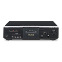
Related product manuals