Do you have a question about the Sony TC-K6111S and is the answer not in the manual?
Lists similar mechanism model names and their corresponding tape transport mechanisms.
Procedure for testing AC leakage from exposed metal parts to earth ground.
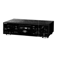
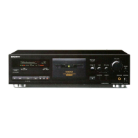
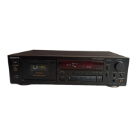
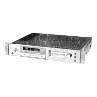
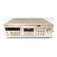
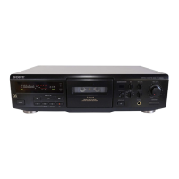
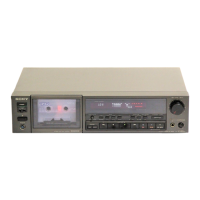
Identifies and describes the front panel controls and indicators of the cassette deck.
Details the procedure for disassembling the mechanism block of the cassette deck.
Explains the steps to remove and disassemble the cassette holder assembly.
Describes how to remove the ornamental plate from the cassette deck.
Details the disassembly of the capstan motor and flywheel for specific models.
Details the disassembly of the capstan motor and flywheel for the TC-K611S model.
Provides instructions for disassembling the reel and assist motors.
Outlines procedures for adjusting the tape path for optimal performance.
Adjustment procedure for the supply pinch roller, typically after replacement.
Details adjustments for the record/playback head, including height, declination, and azimuth.
Covers adjustments for the erase head, including azimuth, height, declination, and depth.
Step-by-step guide for adjusting the azimuth of the record/playback head.
Procedure to adjust the tape speed using a frequency counter.
Method for adjusting playback level using test tapes and a VTVM.
Steps to adjust the record bias for optimal recording performance.
Procedure for setting the record level for accurate audio input.
Adjusting the record equalization for Type IV tapes.
Procedure for adjusting the erase current for specific models.
Illustrates the physical location of various circuit boards within the unit.
Shows the printed wiring board layout for the main section of the device.
Provides the schematic diagram for the audio circuitry of the cassette deck.
Presents the schematic diagram for the system control section.
Displays the schematic diagram for the Dolby S processing section.
Shows the printed wiring board layout for the Dolby S section.
Diagrams illustrating the lead configurations of various semiconductor components.
Exploded view of the front panel components and their part numbers.
Exploded view of the chassis components, including main boards and power supply.
Exploded view of the mechanism section 1, specific to the TC-K611S model.
Exploded view of mechanism section 2 for the TC-K611S model, detailing various parts.
Exploded view of mechanism section 3, covering TC-K707ES and TC-K711S models.
Exploded view of mechanism section 4 for TC-K707ES and TC-K711S, showing parts like motors and gears.
Electrical parts list specific to the Dolby S board, including capacitors, resistors, and ICs.
Lists various miscellaneous parts, accessories, packing materials, and hardware.
| Brand | Sony |
|---|---|
| Model | TC-K6111S |
| Category | Cassette Player |
| Language | English |