4
(GB)
1 Tally lamp
This indicator lights up. The tally control connection is
needed.
For the pin assignment, see “Specifications” on page 10 (GB).
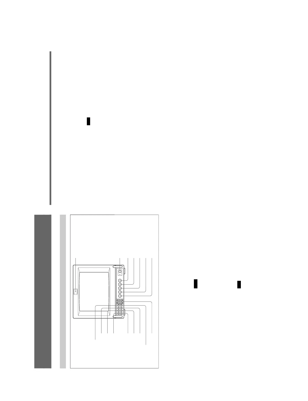
2 POWER switch and indicator
Depress to turn the monitor on. The indicator will light
up in green.
The POWER indicator also functions as the external
power source indicator. When the power supplied
through the DC 12 V IN jack decreases, the indicator
flashes.
3 CONTR (contrast) control
Turn clockwise to make the contrast stronger and
counterclockwise to make it weaker.
4 PHASE control
This control is effective only for the NTSC and
NTSC
4.43
color systems. Turn clockwise to make the
skin tones greenish and counterclockwise to make
them purplish.
5 CHROMA control
Turn clockwise to make the color intensity stronger
and counterclockwise to make it weaker.
6 BRIGHT (brightness) control
Turn clockwise for more brightness and
counterclockwise for less.
7 APER (aperture) control
Turn clockwise for more sharpness and
counterclockwise for less.
Notes
•The PHASE control has no effect on the PAL system,
SECAM system, analog RGB signals, analog
component signals and digital component signals.
•The CHROMA and APER control have no effect on
the analog RGB signals.
8 DEGAUSS button
Press this button momentarily. The screen will be
demagnetized.
Note
If you press the DEGAUSS button again too soon, the
color shades may be uneven.
Location and Function of Parts and Controls
Front
1 Tally lamp
!§ R/G/B BIAS and GAIN
adjustment controls
!∞ 16:9 selector
!¢ H/V DELAY selector
!£ UNDER SCAN selector
!™ BLUE ONLY selector
!º LINE/RGB input selector
9 SYNC INT/EXT (sync
internal/external) selector
8 DEGAUSS button
7 APER (aperture) control
6 BRIGHT (brightness) control
5 CHROMA control
4 PHASE control
3 CONTR (contrast) control
2 POWER switch and indicator
!¡ A/B, SDI/RGB input
selector
5
(GB)
9 SYNC INT/EXT (sync internal/external) selector
Keep this button released (INT) to operate the monitor
on the sync signal from the displayed composite video
signal.
Depress this button (EXT) to operate the monitor on an
external sync signal fed through the EXT SYNC
connector on the rear panel.
When the digital component signal is selected, the
monitor is operated on the internal sync signal.
!º LINE/RGB input selector
This button selects the input signal to be monitored.
Depress this button (RGB) for a signal fed through the
COMPONENT SDI connectors or the RGB/
COMPONENT connectors. Keep this button released
(LINE) for a signal fed through the LINE A or LINE B
connectors.
!¡ A/B, SDI/RGB input selector
When the LINE/RGB input selector is set to LINE,
keep this button released (A) for a signal fed through
the LINE A connectors. Depress this button (B) for a
signal fed through the LINE B connectors.
When the LINE/RGB input selector button is set to
RGB,
this button selects the digital signal or the component
signal fed through the RGB input connectors on the
rear panel. Keep this button released (SDI) for the
digital signal. Depress this button (RGB) for the
component signal or the analog RGB signal.
When this button is depressed, the signal is selected by
setting the RGB/Y R-Y B-Y selector on the rear panel.
!™ BLUE ONLY selector
Depress this button to turn off the red and green
signals. A blue signal is displayed as an apparent
monochrome picture on the screen. This facilitates
“chroma” and “phase” control adjustments and the
observation of video noise.
Note
The PHASE control adjustment is effective only for
NTSC system.
!£ UNDER SCAN selector
Depress this button for underscanning. The display
size is reduced by approximately 3% so that four
corners of the picture are visible.
!¢ H/V DELAY selector
Depress this button to observe the horizontal and
vertical sync signals at the same time. The horizontal
sync signal is displayed in the left quarter of the
screen; the vertical sync signal is displayed near the
center of the screen.
!∞ 16:9 selector
Press this button to monitor the signals of 16:9 picture.
Pressing the UNDER SCAN selector !£ in 16:9 mode
displays the whole 16:9 picture up to the four corners.
!§ R/G/B BIAS and GAIN adjustment controls
Used for white balance fine adjustment.
BIAS and GAIN controls are provided for the R (red),
G (green) and B (blue) screens.
BIAS: Adjust the color temperature and brightness of
the screen at the lowlight.
GAIN: Adjust the color temperature and brightness of
the screen at the highlight.
To adjust them, use a screwdriver with a diameter of
2 mm (
3
/
32
inch).