6
(GB)
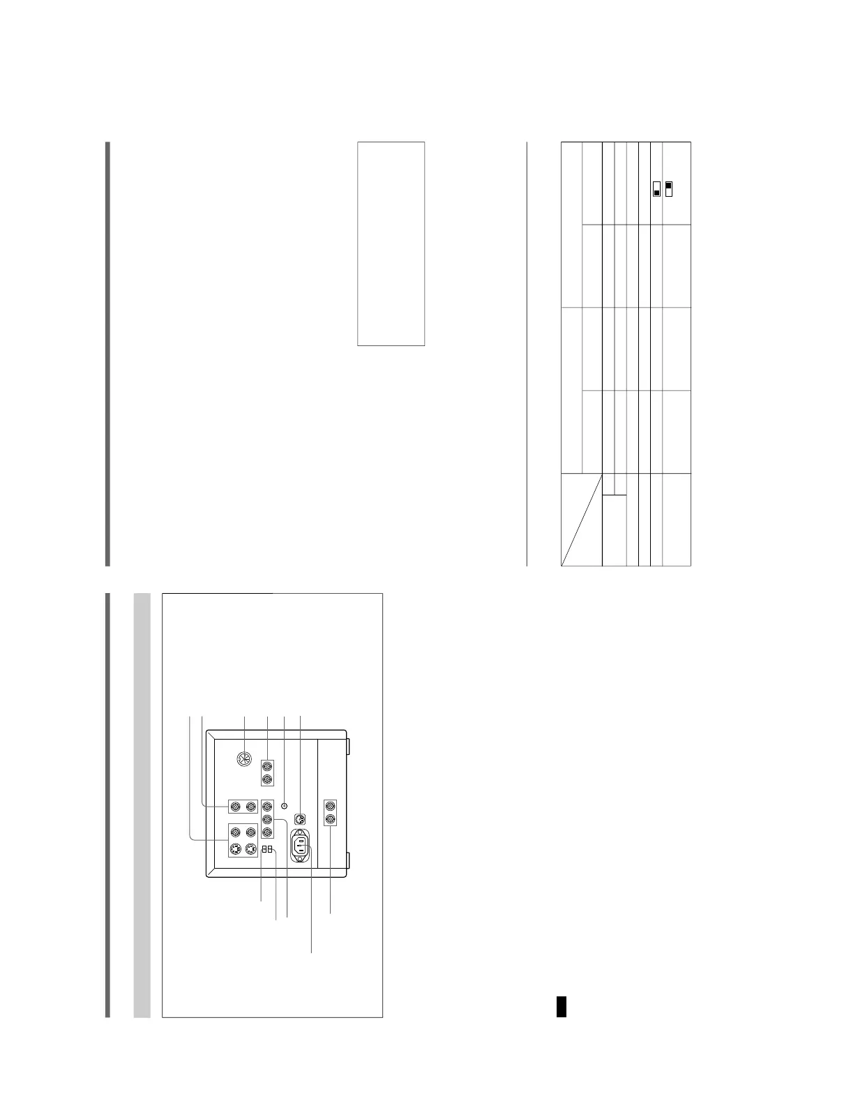
!¶ LINE A IN/OUT connectors
To monitor the signal fed through these connectors,
keep the LINE/RGB input selector and the A/B, SDI/
RGB input selector released (LINE and A).
Y/C IN (4-pin mini DIN): Connect to the Y/C output
of a video camera, VCR or other video equipment.
Y/C OUT (4-pin mini DIN): Loop-through output of
the Y/C IN connector. Connect to the Y/C input of
a VTR or another monitor.
VIDEO IN (BNC): Connect to the video output of a
video camera, VTR or other video equipment.
VIDEO OUT (BNC): Loop-through output of the
VIDEO IN connector. Connect to the video input
of a VTR or another monitor.
Note
When a plug is connected to the Y/C IN connector, the
VIDEO IN connector is automatically disconnected.
!• LINE B IN/OUT connectors
To monitor the signal fed through these connectors,
keep the LINE/RGB selector released (LINE) and
depress the A/B, SDI/RGB input selector on the front
panel (B).
VIDEO IN (BNC): Connect to the video output of a
video camera, VTR or other video equipment.
VIDEO OUT (BNC): Loop-through output of the
VIDEO IN connector. Connect to the video input
of a VTR or another monitor.
!ª REMOTE connector (8-pin mini DIN)
Turning the tally lamp on or off and the input setting
are remotely controlled by connecting another
equipment to this connector.
For the pin assignment of this connector, see
“Specifications” on page 10 (GB).
@º EXT SYNC (external sync) IN/OUT connectors
(BNC)
To use these connectors, depress the SYNC INT/EXT
button on the front panel (EXT).
IN: When this monitor operates on an external sync
signal, connect the reference signal from a sync
generator to this connector. In this case, depress
the SYNC INT/EXT selector (EXT) on the front
panel.
OUT: Loop-through output of the EXT SYCN IN
connector. Connect to the external sync input of
video equipment to be synchronized with this
monitor.
@¢ RGB/Y R-Y B-Y selector
Rear
Location and Function of Parts and Controls
@§ AC IN socket
!¶ LINE A IN/OUT connectors
!• LINE B IN/OUT connectors
!ª REMOTE connector (8-pin mini DIN)
@º EXT SYNC (external sync)
connectors (BNC)
@¡ V HOLD (vertical hold) control
@™ DC 12V IN jack (XLR, 4 pin)
@£ COMPONENT LEVEL selector
@¶ COMPONENT SDI IN/OUT
connectors (BNC)
@∞ RGB/COMPONENT input
connectors (BNC)
7
(GB)
@¡ V HOLD (vertical hold) control
Turn to stabilize the picture if it rolls vertically.
After the picture is stabilized, display another signals
and adjust this again so that the picture is stabilized
even when another signal is selected.
@™ DC 12V IN jack (XLR, 4 pin)
Connect the DC 12 V power source to operate this
monitor.
@£ COMPONENT LEVEL selector
Select the component level from among two modes.
N10/SMPTE: for 100/0/100/0 signal
BETA 0 : for 100/0/75/0 signal
@¢ RGB/Y R-Y B-Y selector
RGB: Set to this position to input the analog RGB
signal.
Y R-Y B-Y: Set to this position to input the
component signal.
@∞ RGB/COMPONENT input connectors (BNC)
To monitor a signal fed through these connectors,
depress the LINE/RGB input selector on the front
panel (RGB) and the A/B, SDI/RGB input button
(RGB). When the SYNC INT/EXT selector on the
front panel is released (INT), the monitor operates on
the sync signal from the G/Y channel.
•To monitor the analog RGB signal
Connect to the analog RGB signal outputs of a
video camera. Depress the A/B, SDI/RGB input
selector on the front panel (RGB).
Set the RGB/Y R-Y B-Y selector @¢ on the rear
panel to RGB.
•To monitor the component signal
Connect to the Y/R-Y/B-Y component signal
outputs of a Sony BetaCam video camera. Depress
the A/B, SDI/RGB input selector on the front
panel (Y R-Y B-Y). Set the RGB/Y R-Y B-Y
selector @¢ on the rear panel to Y R-Y B-Y.
@§ AC IN socket
Connect the supplied AC power cord to this socket.
@¶ COMPONENT SDI IN/OUT connectors (BNC)
Depress the LINE/RGB input button (RGB) and
release the A/B SDI/RGB input button (SDI) on the
front panel.
IN: Inputs SMPTE 259M/CCIR 656-III 4:2:2 serial
digital signals from Digital BETACAM VTRs,
etc.
OUT: Outputs the digital signal of the equipment
connected to the COMPONENT SDI IN
connector (Active through).
We recommend to connect the following cable to
this connectors.
Coaxial cable: 5C-2V (Max. 200 m, 656 feet)
Fujikura America Inc., Fujikura
Europe Ltd (FEL) or the equivalent
Relationships between the selectors, connectors and the input signal
The input signal is changed by the selectors and connectors on the front and rear panels as listed below.
Selectors and
Front panel Rear panel
connectors
Input signal A/B, SDI/RGB input LINE/RGB input Input connector RGB/Y R-Y B-Y
selector !¡ selector !º selector @¢
COMPOSITE
AA ø LINE ø LINE A (VIDEO) —
BB Ø LINE ø LINE B —
Y/C A ø LINE ø LINE A (Y/C) —
COMPONENT SDI SDI ø RGB Ø COMPONENT SDI —
ANALOG RGB RGB Ø RGB Ø RGB/COMPONENT RGB
COMPONENT
Y
(Y R-Y B-Y)
RGB Ø RGB Ø RGB/COMPONENT R-Y
B-Y