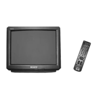
Do you have a question about the Sony Trinitron KD-28DX51U and is the answer not in the manual?
Explains basic TV operations and functions using the remote control.
Guides users through the initial TV setup and channel tuning process.
How to locate the signal from connected video equipment like VCRs.
How to switch between digital and analog TV reception modes.
Explains how to use various remote control buttons for TV functions.
How to access and view digital text services provided by broadcasters.
How to access and view analogue text services, typically via page 100 index.
Explains how to use Fastext for quick navigation of text pages.
Explains the purpose and benefits of the Digital EPG.
How to use the category list to filter channels in the EPG.
Details on how to set up programme recordings using the EPG.
Explains how to adjust picture settings like contrast, brightness, and color.
Guides on adjusting sound settings such as treble, bass, and balance.
Options for fine-tuning audio features like Dolby Virtual and Auto Volume.
Configure subtitles, audio languages, parental locks, and technical settings.
Learn how to perform auto tuning, edit the program list, and manually tune channels.
How to view VCR content, with or without a fully wired scart lead.
How to view content from devices connected to the TV's rear input ports.
How to view content from devices connected to the TV's front input ports.
Instructions for removing the rear cover of the TV set.
Procedures for removing and reattaching the main chassis assembly.
Step 1 of removing the A Board from the chassis.
Step 2 of removing the A Board from the chassis.
Instructions for removing the F3 Board.
Instructions for removing the A1 Board.
How to position the chassis for servicing specific boards.
Instructions for removing the N Board.
Detailed procedure for removing the CRT picture tube, including safety precautions.
How to remove and refit bottom plates on the main bracket for servicing.
Adjusting beam landing for optimal picture geometry and color alignment.
Adjusting color convergence for accurate red, green, and blue beam alignment.
Adjusting focus control for sharp and clear picture display.
Adjusting screen grid (G2) and white balance for proper picture brightness and color temperature.
Detailed steps for adjusting horizontal and vertical static convergence.
Using BMC magnets to adjust dot positions for convergence.
General geometry adjustments including YCH and TLV.
Correcting corner convergence defects using permalloy magnets.
Detailed steps for adjusting the focus control for optimal screen clarity.
Procedures for adjusting screen G2 and white balance in service mode.
Performing service adjustments using the remote commander.
Step-by-step guide to accessing the TV's service mode.
Geometry adjustment parameters available in the service menu.
Intermediate Frequency (IF) adjustment parameters.
Adjustments related to the TV's deflection system for image geometry.
Adjusting sub-brightness settings in the service menu.
Adjusting sub-contrast settings in the service menu.
Adjusting sub-colour settings for accurate color reproduction.
Block diagram for the B1 board (Y,U,V Switching).
Block diagram for the C board (R,G,B Out).
Block diagram for the D2 board (Smart Mode Deflection).
Block diagram for the F3 board (Lightning Discharge, Fuse, Line Filters).
Block diagram for the F5 board (AC Input, LED, SIRCS).
Block diagram for the H5 board (Headphone, SVHS and Phono).
Block diagram for the VM board (Velocity Modulation).
Block diagram for the A1 board (Digital Front End Processing).
Part 1 of the block diagram for the A board (Power Supply, Audio).
Part 2 of the block diagram for the A board (Deflection, Power Supply).
References to schematic diagrams and printed wiring boards for various TV boards.
Table of IC voltage readings for the A Board.
Waveform examples for the A Board.
Table listing semiconductor locations for A1 Board side A.
Table listing semiconductor locations for A1 Board side B.
Difference table for components on the A1 Board.
Voltage readings for semiconductors on the C Board.
Difference table for components on the C Board.
Voltage readings for ICs on the C Board.
Waveform examples for the C Board.
Difference table for components on the D2 Board.
Difference table for components on the VM Board.
Block diagram for IC501 (STV9379A) on the A Board.
Block diagram for IC401/IC531 (LM393DT) on the A Board.
Block diagram for IC601 (MCZ3001D) on the A Board.
Block diagram for IC1201 (TDA7495S) on the A Board.
Exploded view of the TV chassis and its main components.