Do you have a question about the Sony TRINITRON KV-G142M and is the answer not in the manual?
Detailed technical data for power, system, dimensions, and weight.
Important cautions regarding electrical safety and component handling.
Abstract of operating instructions from the main manual.
Instructions for connecting VHF, UHF, or indoor antennas to the TV.
Guidance on connecting VCRs, game consoles, or other AV devices.
Steps for automatically scanning and storing TV channels.
Procedure for manually tuning and saving TV channels.
Method for rapid channel setup using specific button combinations.
Turning the TV on, off temporarily, or completely off.
Displaying on-screen info, setting wake up and sleep timers.
Switching between TV broadcast and external video sources.
Choosing predefined picture display settings like Standard or Dynamic.
Adjusting picture parameters like brightness, contrast, and color.
Resolving problems like no picture, no sound, or poor picture quality.
Step-by-step guide for removing the rear cover of the TV.
Instructions for detaching the A board from the TV chassis.
Procedure for removing the F1 board during servicing.
Guidance on setting up the TV for servicing or repair.
Guidance on replacing internal TV components like buttons or light guides.
Procedure for removing the terminal board bracket assembly.
Steps to safely remove the demagnetization coil from the CRT assembly.
Instructions for safely removing the television's picture tube.
Important safety and handling instructions for the picture tube anode cap.
Aligning the electron beams for correct color purity and convergence.
Required tools like pattern generator, degausser, and oscilloscope.
Correcting the alignment of red, green, and blue electron beams.
Adjusting the clarity and sharpness of the picture by controlling electron beam focus.
Setting screen grid voltage and adjusting color balance for optimal picture.
Methods for entering service mode, writing data, and confirming adjustments.
Table indicating flickering frequency for identified board failures.
Performing circuit adjustments using the RM-869 remote commander.
Step-by-step guide for adjusting specific items using service mode.
Table detailing adjustable items, their ranges, and functions.
Specific notes and configurations for optional adjustment items.
Procedure for adjusting the A board after replacing the IC003 memory chip.
Correcting geometric distortions in the TV picture display.
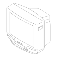
Diagram showing the physical layout and part identification of the TV chassis.
Notes on components critical for safety, marked with shading and marks.
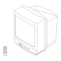
Information and part numbers for the RM-869 remote commander.